1. Principles and practices
2. Project management
3. Computer Aided design
4. Computer controlled cutting
5. Electronics production
6. 3D Scanning and printing
7. Electronics design
8. Computer controlled machining
9. Embedded programming
10. Mechanical Design
11. Input devices
12. Molding and Casting
13. Output devices
14. Networking and communications
15. Interface and application programming
16. Wildcard week
17. Applications and implications
18. Invention, intellectual property and income
19. Project development
13. Output devices
Assignment:Group assignment:
Measure the power consumption of an output device
Document your work (in a group or individually)
Individual assignment:
Add an output device to a microcontroller board you've designed and program it to do something
Planning
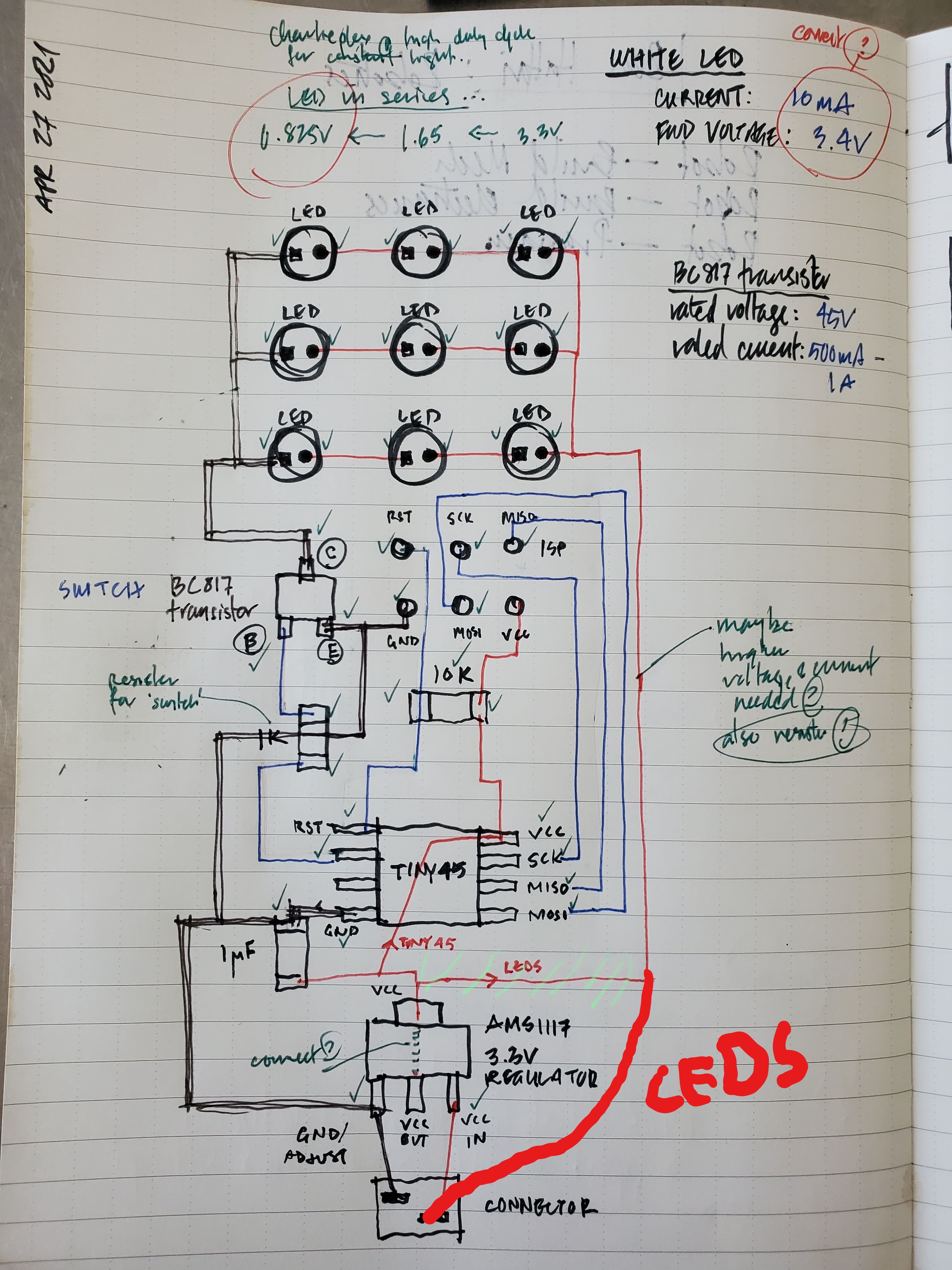
This time I decided to have fun with my board. I took an example by Neils hello LEDs board and remade it but with an Attiny45 because this is what I had on hand. I'd like to use special "Party LEDs" because I love them- they make me laugh.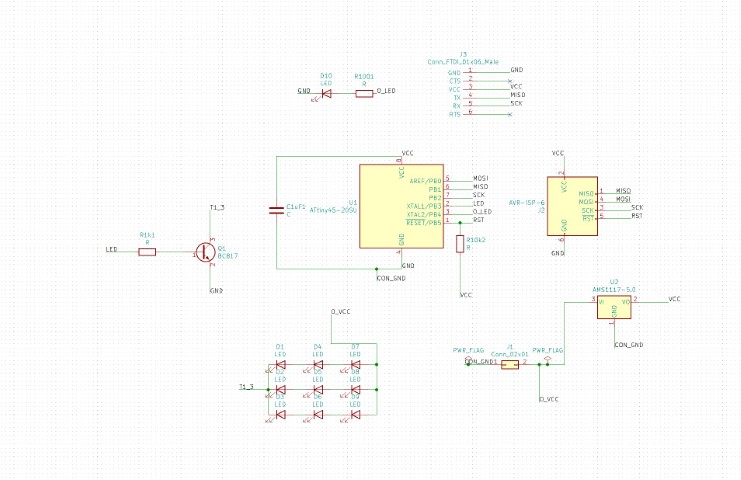
Here are the parts:
- 1 SMD Capacitor 1uF (1206)
- 9 THT LEDs (automatic random colors)
- 1 SMD LED in green (1206)
- 1 02x01 connector (this one was trash I soldered my battery pack directly to the board)
- 1 ISP SMD Pinheader (2x03, 2.54mm)
- 1 FTDI 01x06 Male Pinheader (2.54mm)
- 1 BC817 Transistor
- 1 100 Ohm SMD Resistor (1206)
- 1 10K Ohm SMD Resistor (1206)
- 1 1K Ohm SMD Resistor (1206)
- 1 ATTiny45-20SU
- 1 AMS1117-5.0 Voltage converter (9v to 5v)
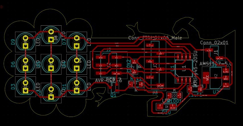
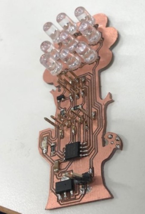
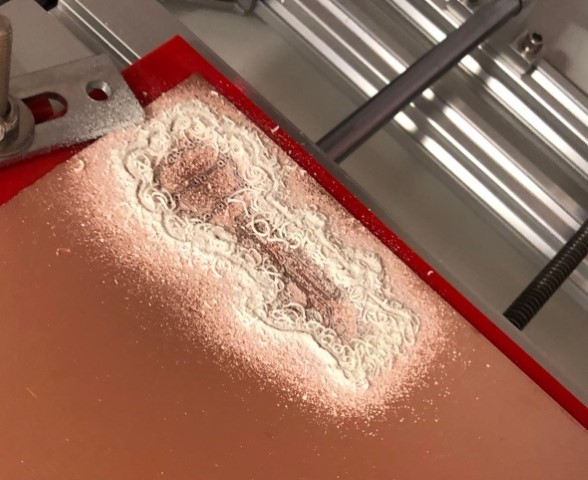 Jokes aside- here you can see the finished board:
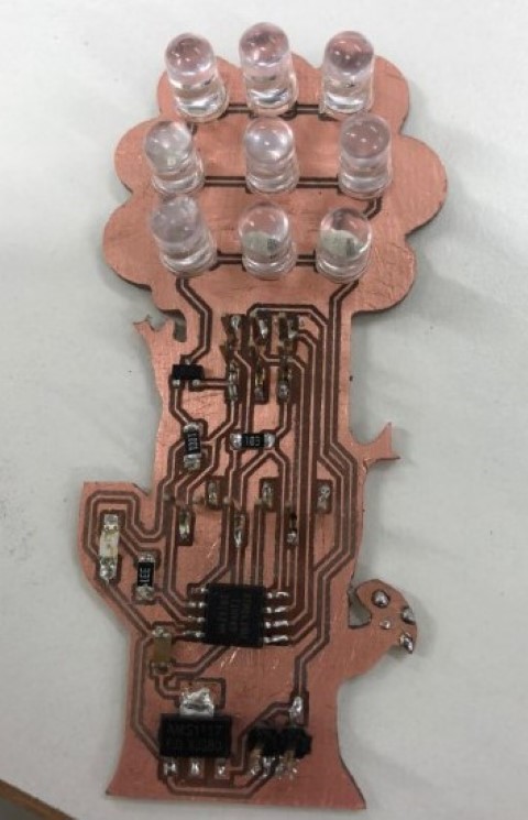
Programming
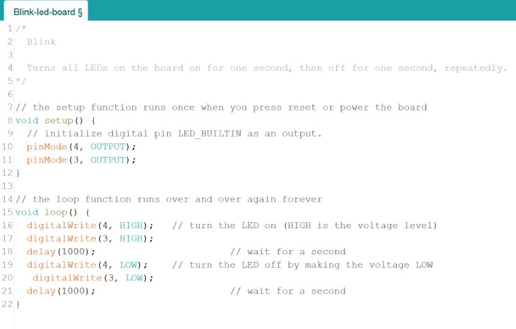
Before I programmed it, I needed to test if the board was even alive. So I flashed the usual blink program. It worked as you can see: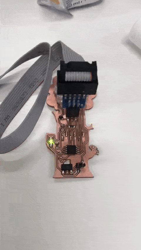
Perfect. After that I figured out a programm to let my "party" LEDs blink together with the onboard LED:
Problems I had
Before that damn board worked, I had problems (as always). This time I was visually tricked by the solder! I tested the connection with a multimeter and it worked. But as soon as I tried to flash the board- it didn't work. I was totally confused by that until I pulled that black plastic off and saw that two pins weren't properly soldered and I didn't realize it because I was pressing the pin unwillingly down while testing it with the multimeter.It also visually looked like it was properly soldered because the solder was on top of the pin so it looked normal. The pads are also really small so it wasn't possible to widen the solder so it can be visually seen. But I somehow managed to do it.
Testing
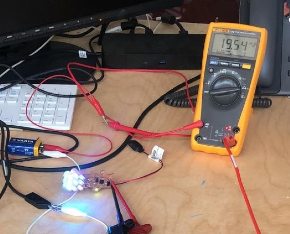
I tested it with a 9V battery block, and it worked as you can see here: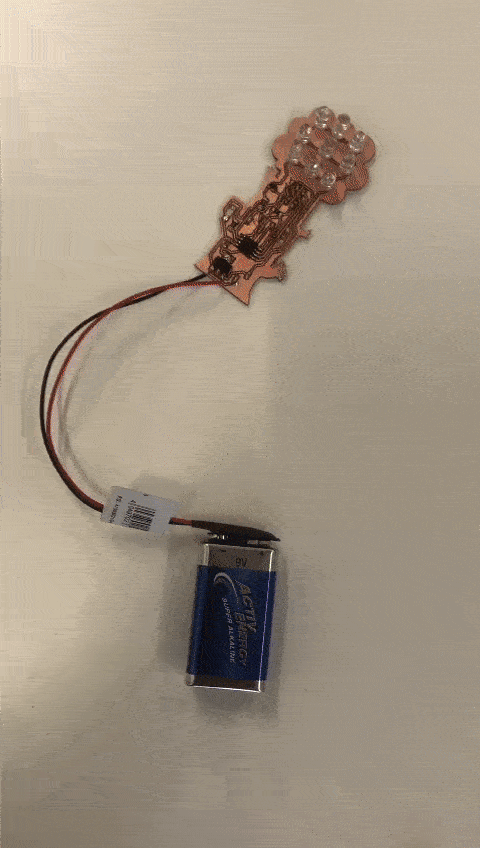
Group Assignment
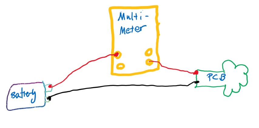
I made the group assignment myself, because I needed to know how much voltage and ampere I need for lighting up all those LED's. Since the ATTiny doesn't need so much (it tolerates up to 5V) and I have a different circuit for the LEDs, I needed to know how much voltage they need.Here you can see a lovely sketch from Rico, who helped me with this assignment.
 As you can see the red line represents VCC and black GND. You can see here the error of my first board, the VCC needed to be directly connected to the LED so that they can get more voltage than the microcontroller. But how much Voltage do they need?
In the video below you can see how we tested and measured the output.
As you can see the red line represents VCC and black GND. You can see here the error of my first board, the VCC needed to be directly connected to the LED so that they can get more voltage than the microcontroller. But how much Voltage do they need?
In the video below you can see how we tested and measured the output.
So seemingly 9V was already enough despite thinking 12V was necessary for the leds. Now to the ampere. I connected everything like this and used the mA setting on the multimeter:
And this is what it looked in practice.
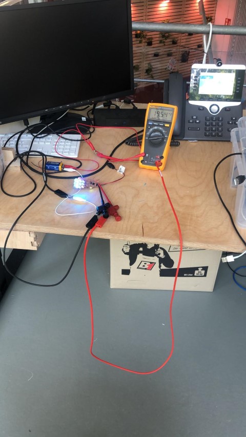 And this is how much ampere I need for the LEDs: