Assignments
1. Principles and practices
2. Project management
3. Computer Aided design
4. Computer controlled cutting
5. Electronics production
6. 3D Scanning and printing
7. Electronics design
8. Computer controlled machining
9. Embedded programming
10. Mechanical Design
11. Input devices
12. Molding and Casting
13. Output devices
14. Networking and communications
15. Interface and application programming
16. Wildcard week
17. Applications and implications
18. Invention, intellectual property and income
19. Project development
4. Computer controlled cutting
Assignment: Design, lasercut, and document a parametric press-fit construction kit, which can be assembled in multiple ways. Account for the lasercutter kerf. cut something on the vinylcutter.Vinyl Cutting
So, we currently only got Silhouette vinyl cutters (portrait and cameo 3) in our lab, that's why I'm using the Cameo 3. It has a bigger cutting surface than the portrait but they use the same software: Silhouette Studio. There are a bunch of other versions of this software (e.g. for designers, for businesses), but I'm using the free one. With Silhouette Studio you can create designs and send to a Silhouette machine. Let me show you how I did it!Design
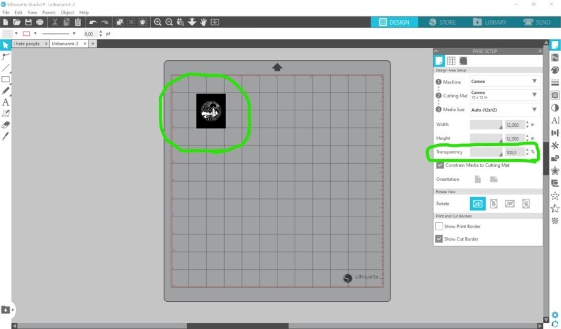
First, I loaded a pic (.jpg or .png works well) into Silhouette Studio. After that, I traced it with the tracing tool. DON'T CHANGE THE PIC SIZE because it'll get pixly!
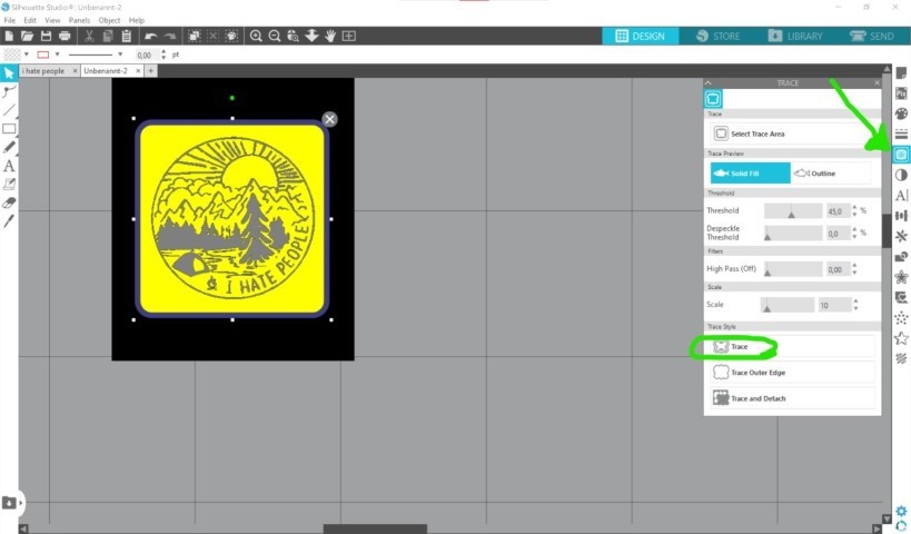
As you can see in the picture above, the tracing tool looks like a little butterfly (yes the german word for it is indeed Schmetterling), just click on it and a small window will open. There you can click and drag your mouse over your desired motif and inspect it. Does the program recognize it? If not, just move the little controllers until the tracing image looks good. Now we're ready for tracing! Click on the trace button and let the magic happen.
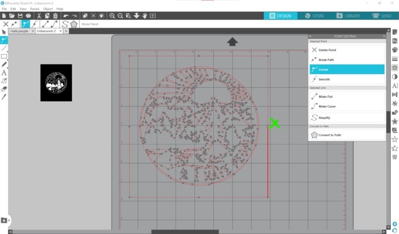
Now your image is traced and you can see a neat path drawing. I personally don't want a border so I delete it.
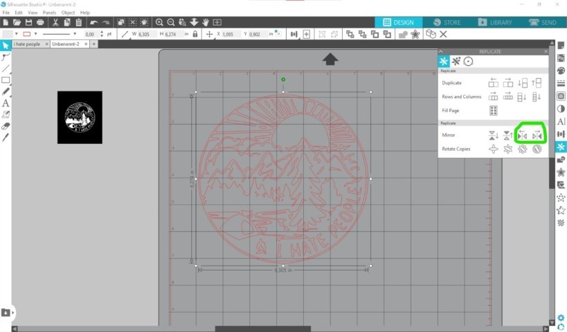
If you're satisfied with your result, you can leave it as it is. However, if you want to transfer it on textile (using a heat transfer foil of course) you need to flip it! This is possible using the ninja star looking button. Now flip it horizontically (y'know to the left or right).
Instead of flipping the original path, the program will create a mirrored copy. You can move the originial outside of the working space, the program will ignore it.
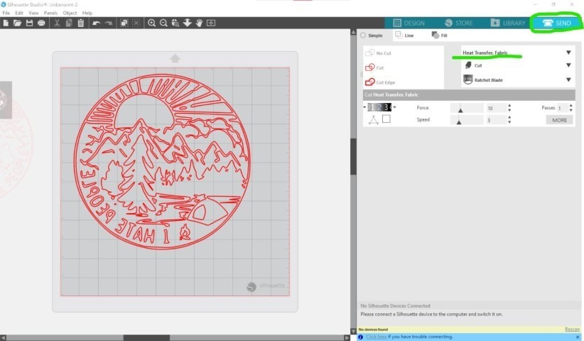
Now you can send it to the machine. Select your desired material (heat transfer for me) and make sure it it set to cut. If you connect the machine for the first time, it might take a while for your computer to recognize it. If you hit "send" it'll send it to the machine and it will immediately cut so make sure everything is set up well.
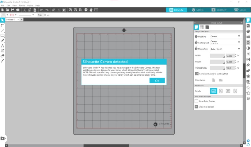
Here you can see what it looks like when the computer recognizes the machine.
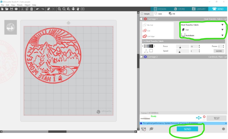
Here you see what it looks like when you're able to hit "send".
Machine setup
For this you need: a cutting mat and some foil. Cut the foil to the fitting size and stick it to the mat. If you're using heat transfer like I do, you need to put it shiny side down.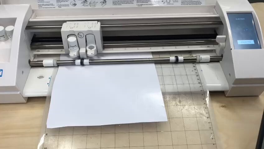
Now hold the mat against the roller, right next to the blue line and tap on insert on the machines touch display (or something similar, depends on language setting). This is the time where you hit SEND on the silhouette software.
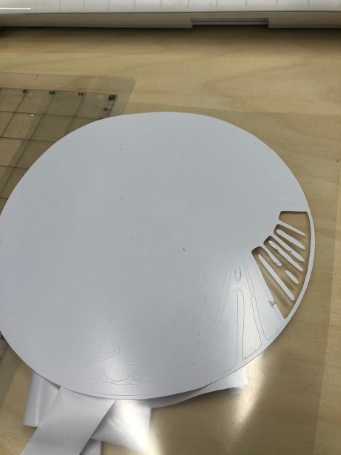
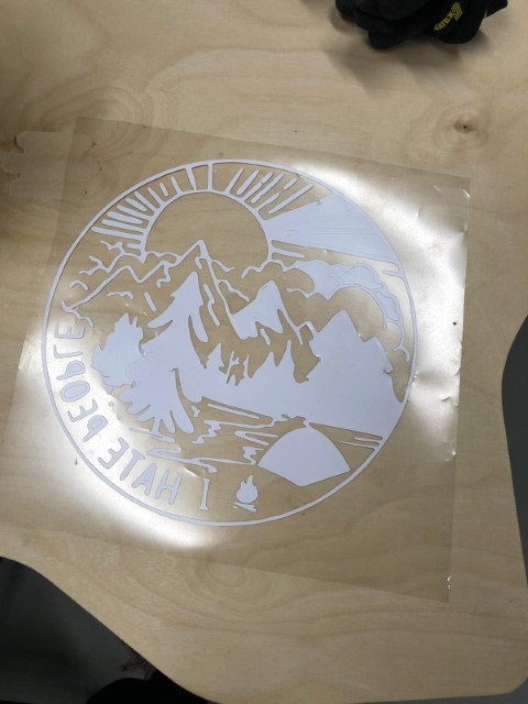
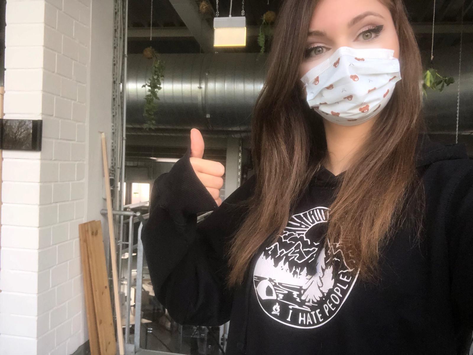
This is the result, now it's necessary to pull everything which doesn't belong to the motif out. Almost done here. If it's finished I plan to put it on a hoodie. And here it is:
Parametric Press-fit Construction
I wanted to make a pet house (parametric, so I can make multiple sizes). And I'd like to cut it out in cardboard. I'm not sure how much cardboard we have in stock, so I might need to do it with wood. Here you can see my initial sketch: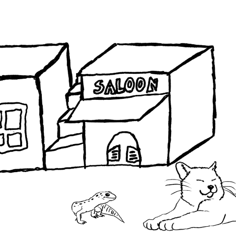
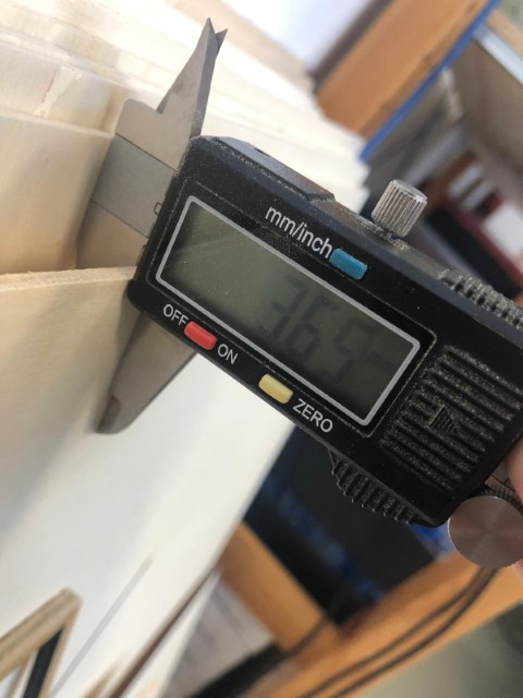
First, I need to look for tolerances. I measured the wood I'd use. I planned to use cardboard first, but the cardboard we had, had an irregular thickness (probably due to pressure). The thickness was "3.65mm".
I started to use my beloved lasercutter from Epilog, a Zing 1060. Well, it is a "Bazinga" cutter to be exact- I glued that on there a few years ago because I thought it was funny.
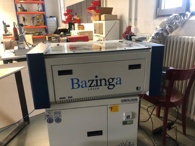
That's when I realised that my Design was too big for it. Yes, sometimes my brain has too many tabs open and sometimes it needs time to defragment (which I don't have).
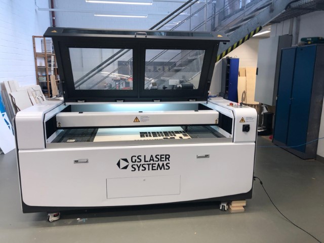
However, I switched to this beauty from GS LASER SYSTEMS (GS 100160 PR).
Oh well, I tested both to compare them. Here you can see that my 3.65mm board fits into the 3.4mm slot from the bazinga and in the 3.2mm slot from the big laser. This was a huuge difference. But no problem, my design will be parametric, hehe.

So to do my parametric design, I used Autodesk Fusion360 again. I'd like to get better in using it.
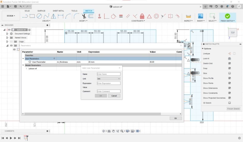
I created a sketch in fusion, went to the "modify" section of the toolbar, hit "change parameters" and this window came. Now I could create some parameters, for example "material thickness". If it's 4mm you want to fill in the name (e.g. m_thickness), the length (4) and that's it. In the comment section you can write something like "thickness of the material" to explain it further (quite handy in case you forgot what your designation means).
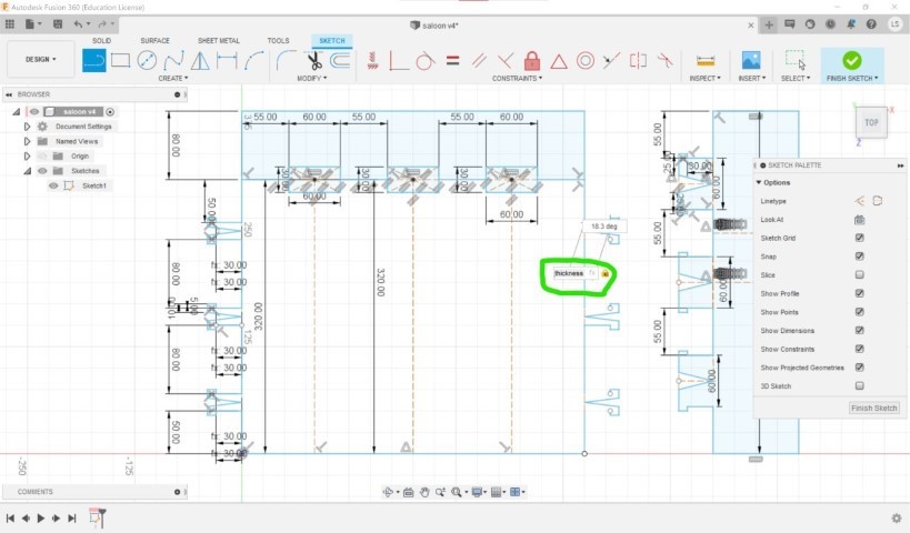
Now you can write you parameter designation into the field where you usually put your measurements and fusion will automatically set the length to your parameter length.
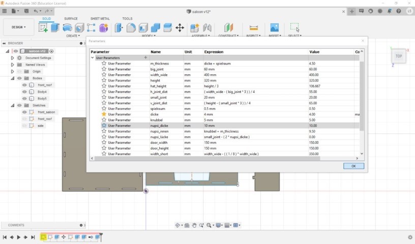
You can also make your parameters interdependent by having them calculated within a parameter definition as seen in the picture above. And this is my finished base:
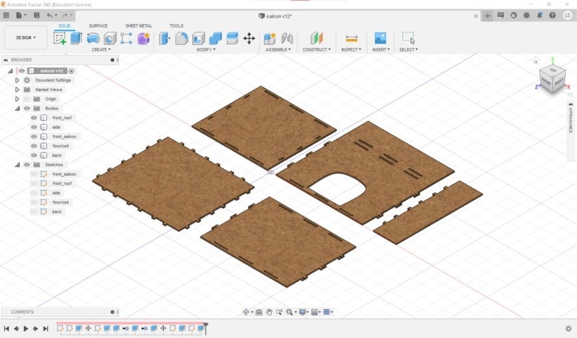
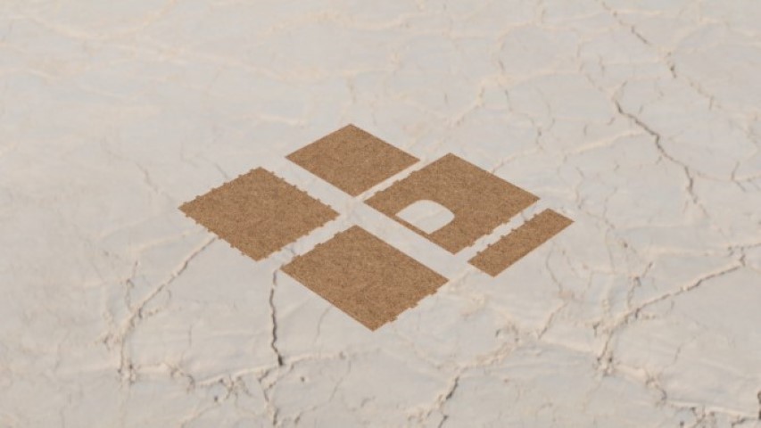
Now since I fell in love with rendering last week, I had to render this as well, even if it doesn't look as good since it's quite flat.
Now, extra stuff is missing, I'd like to have variation in the walls. But for now, that's it!
Soo my design was a little trash. My so called "Nupsies" (the press fit joints) were crappy designed (too big too, round)- so I switched it to an arrow design. Here you can see my end-result. Maybe I'll make more connections and stuff so that its possible to create a big labyrinth. But since I only had one day in the lab, it wasn't possible to test it.
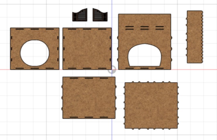
How to cut stuff out
I used our big lasercutter, as I explained before. We got a software called RDWorks to use with our cutter. This is what it looks like: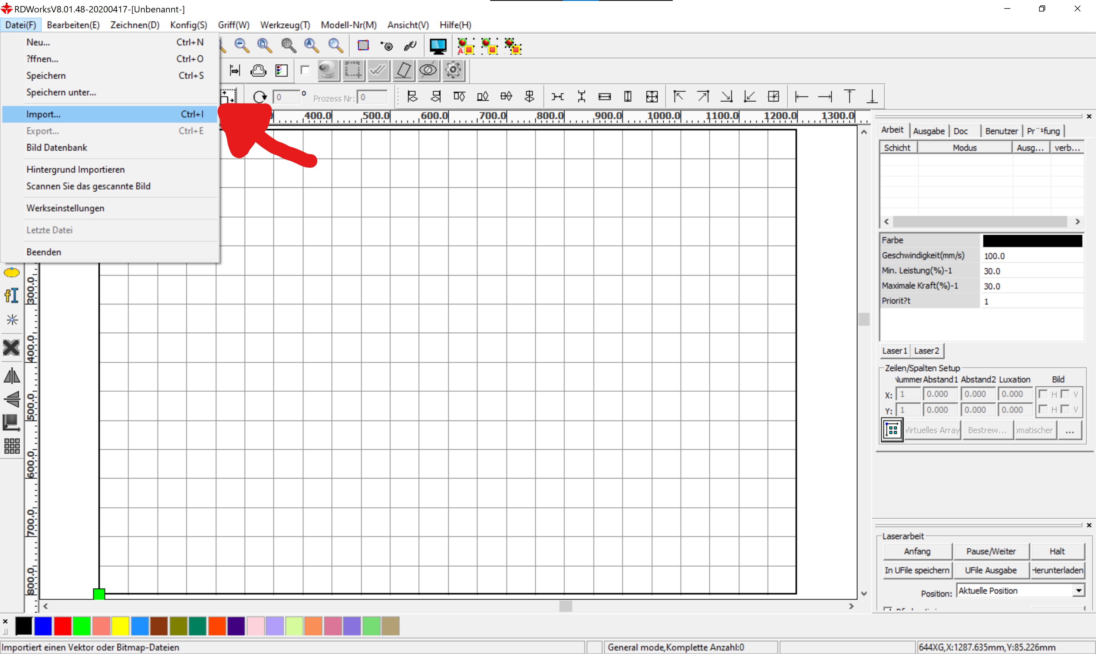
You can click on file>import to import your stuff. First you need to save your svg as dxf or else the program wouldn't be able to import it. I used Inkscape for that.
To be able to engrave and cut in one job, you have to select everything you want to engrave and color it a different color that your cut. Then you can alter the numbers in the little window to your desired laser strength and speed.
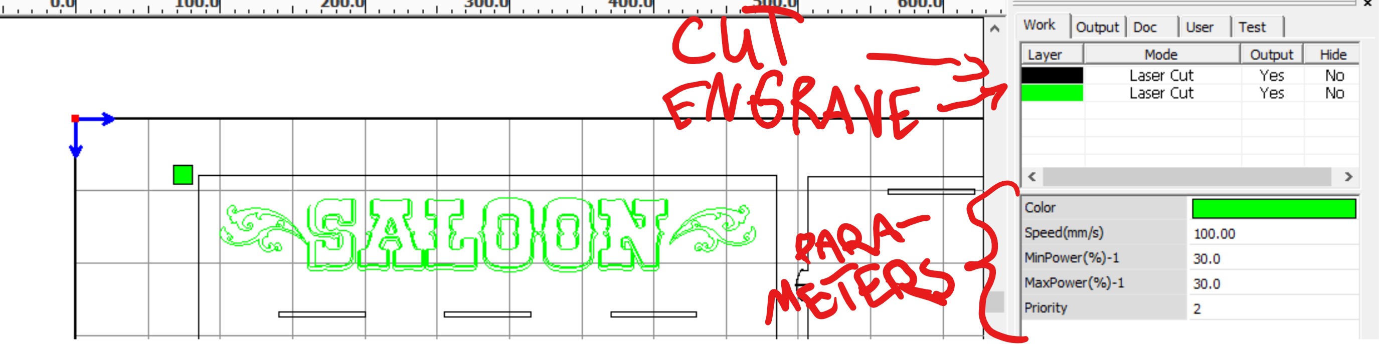
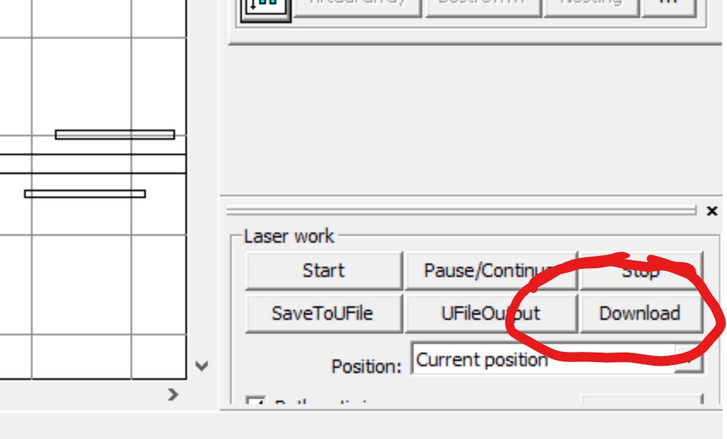
If you're done with that, you can go to "download" and send the data to the lasercutter.
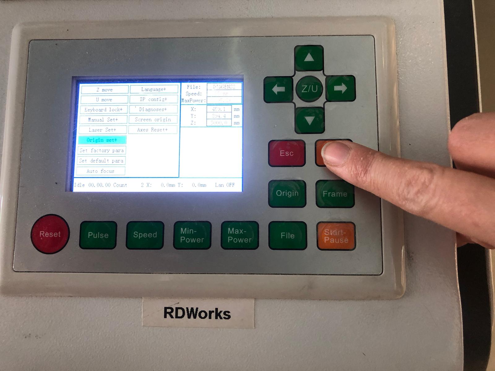
Before cutting you need to set 2 things: The origin and the focus. The focus can be leveled like so:
First put the piece you'd like to cut into the Cutter. Close the lid, turn the laser on.
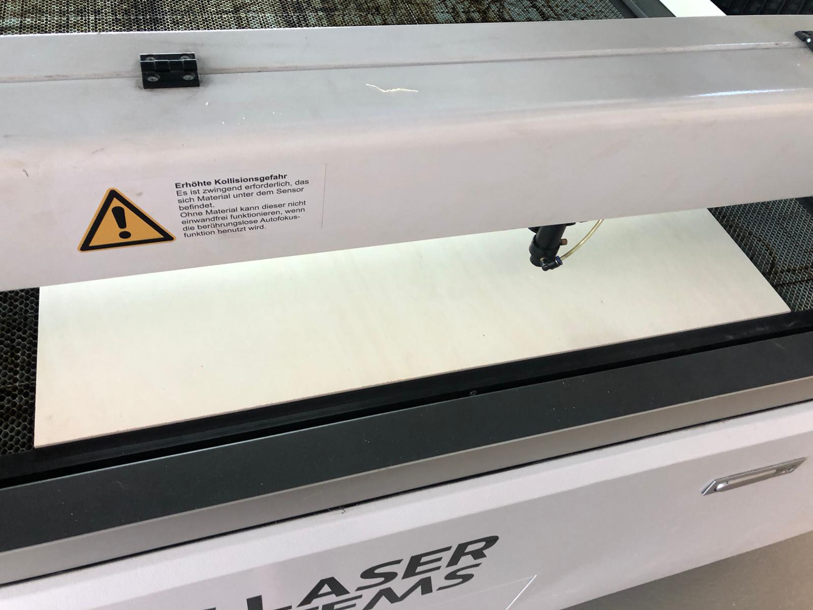
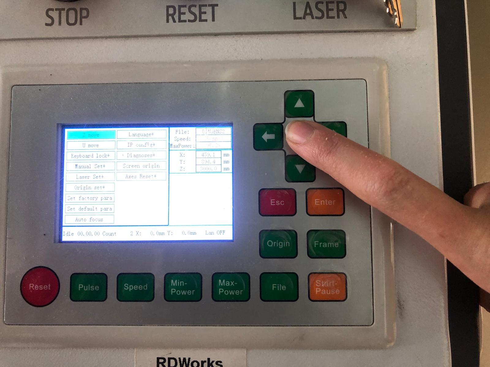
Move to the position where your material is using the arrow keys. Press on the middle button to get to the menu and then navigate to the option "autofocus". Press enter.
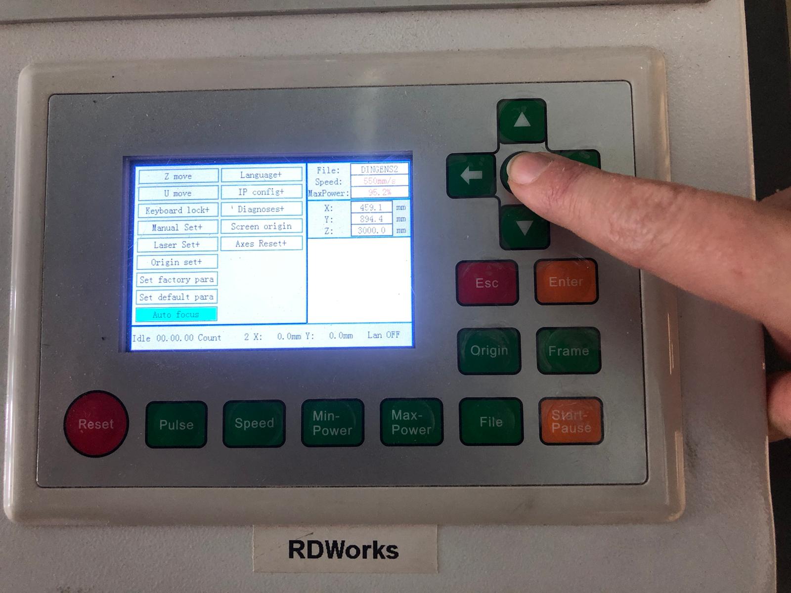
Press enter.
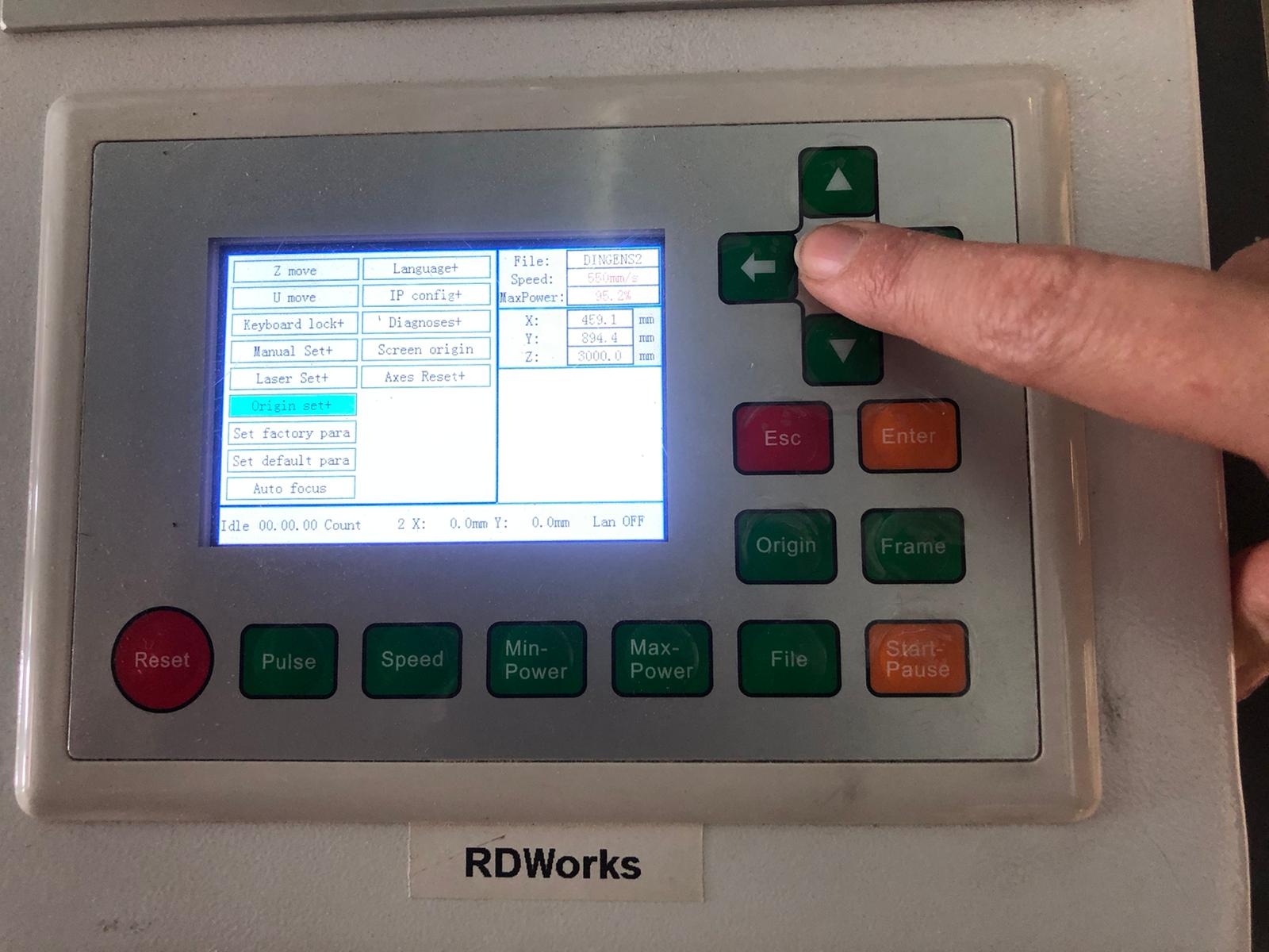
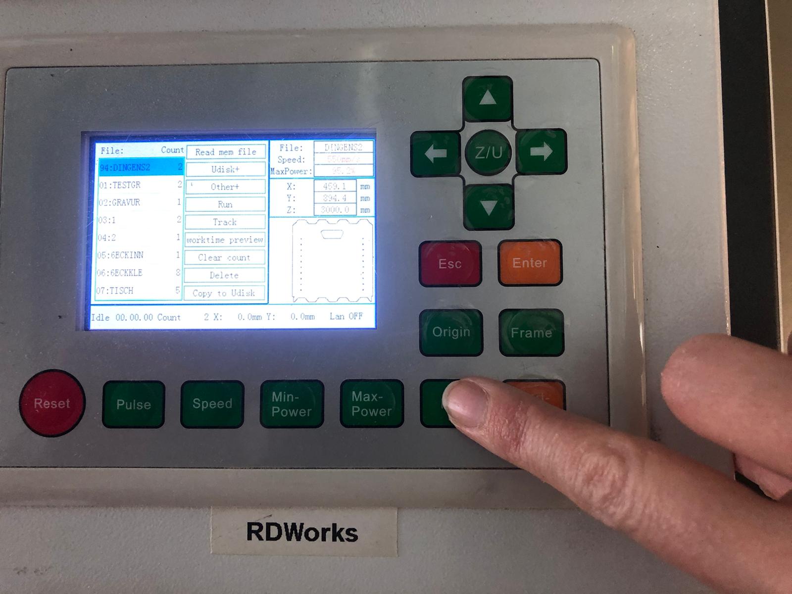
After that is done, you need to set the origin or else the laser will cut anywhere where it cutted before. To do this, go to the menu as well. Set the origin by navigating to the upper right corner of your material using the arrow key. Press enter. After that you can start your job by pressing "start".
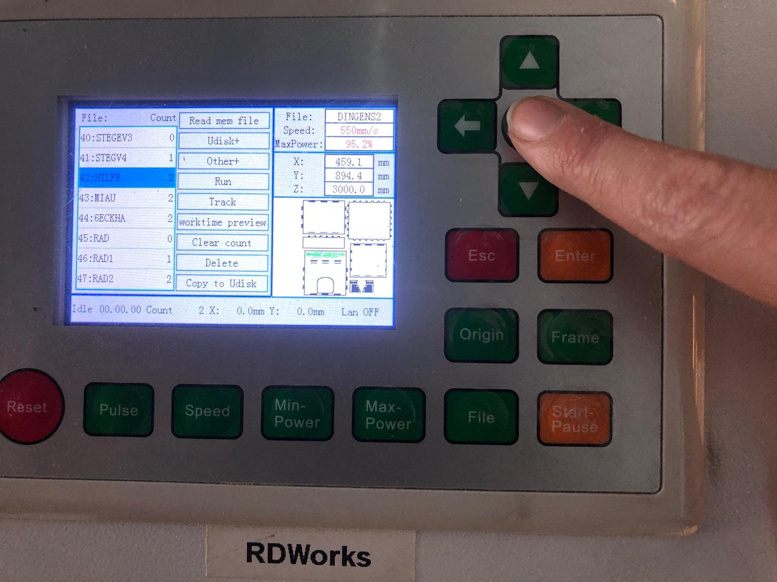
When you want to cut your design again you can press "file", search your design and press enter.
Here you see why I love vectorizing letters:
Sooo fast! And here you can see the result.
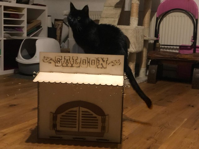
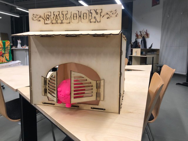
The test kitty liked it. And here are our lab toys posing with the saloon. I didn't think of the lack of cowboy hats, so I didn't print some and I regret it.
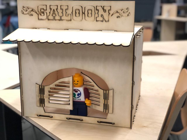
Fun fact: I winged the bendable wood parts in the doors, this was the easiest thing my brain came up with. The other ones I remembered were rather complicated. So I suggest this line pattern.
Extra:
Here you can see what happened in my brain: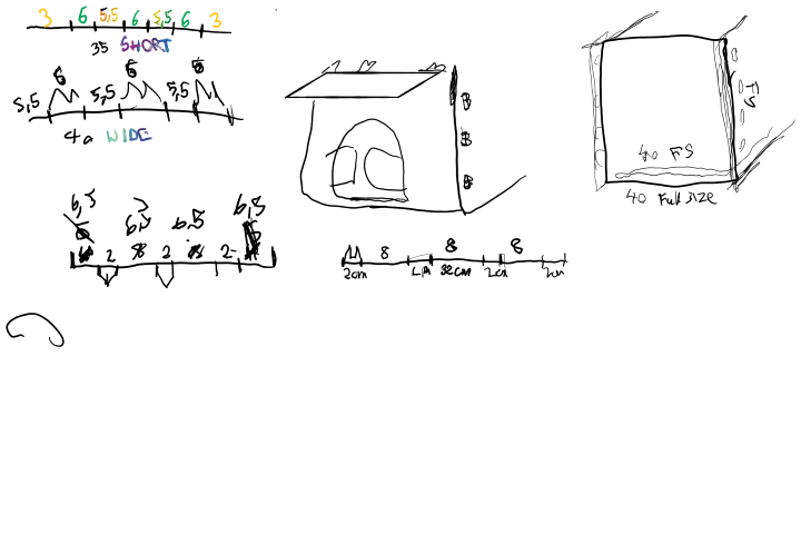
Parametric 2D-Design
Even though I was able to export my 3D- files to 2D using the shaper tool extension for Fusion360, it's also possible to make entirely 2D parametric SVG's using Inkscape. Here you can see that I start resizing my working area since I need enough room for my piece.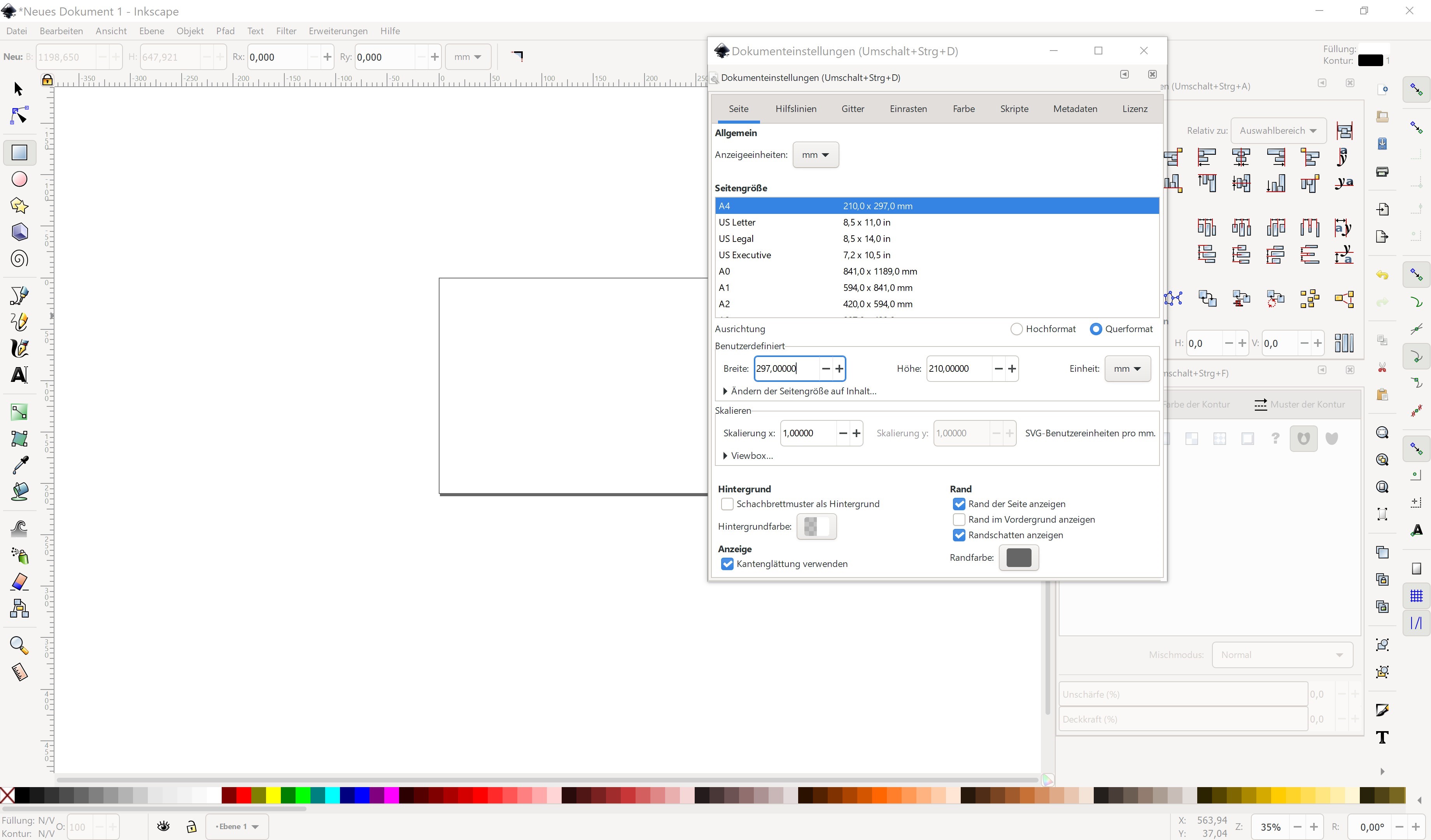
After that I drew a simple rectangle, using the rectangle tool. I wanted to make a housing for our machine which we will build in Week 10.
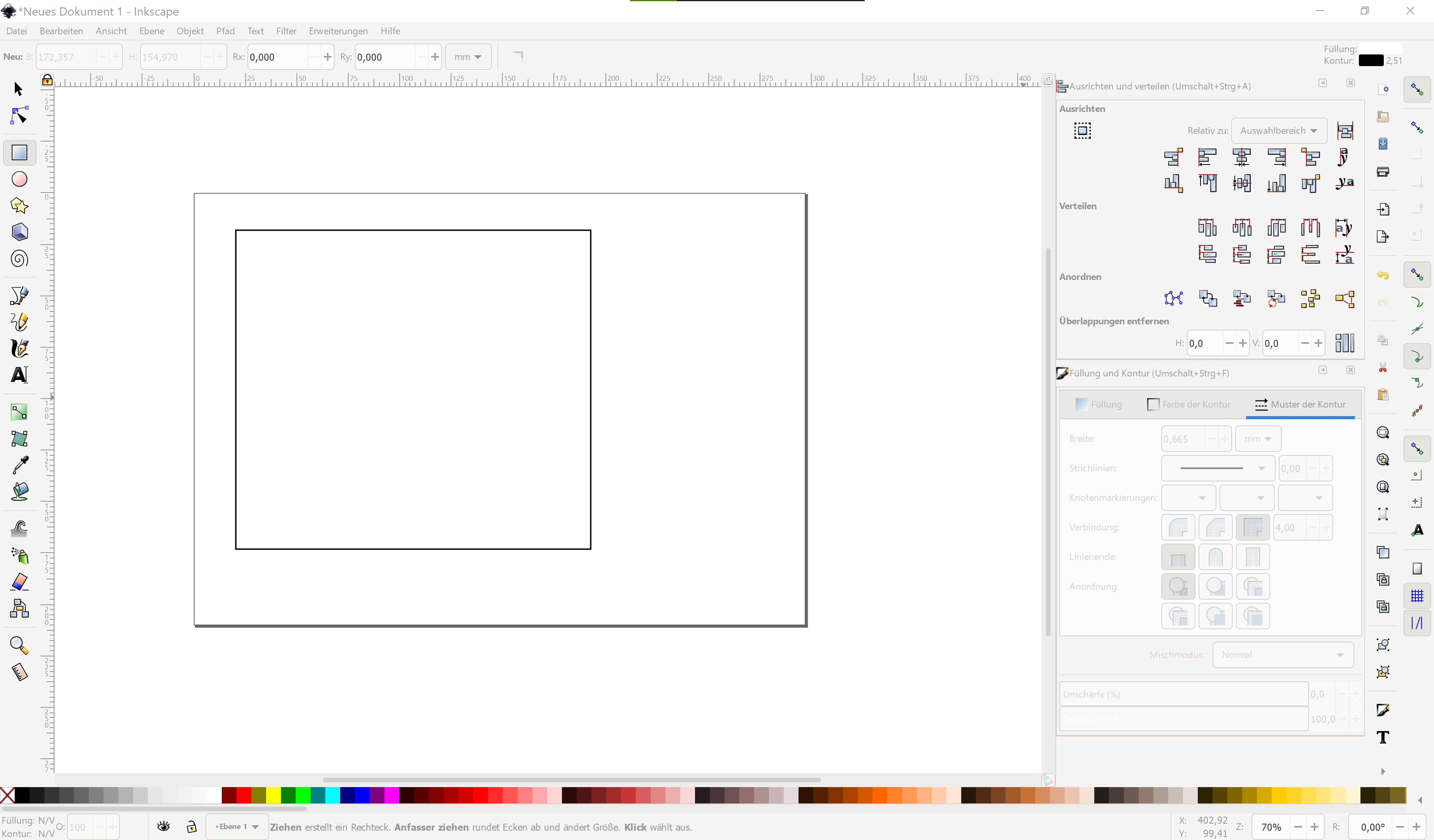
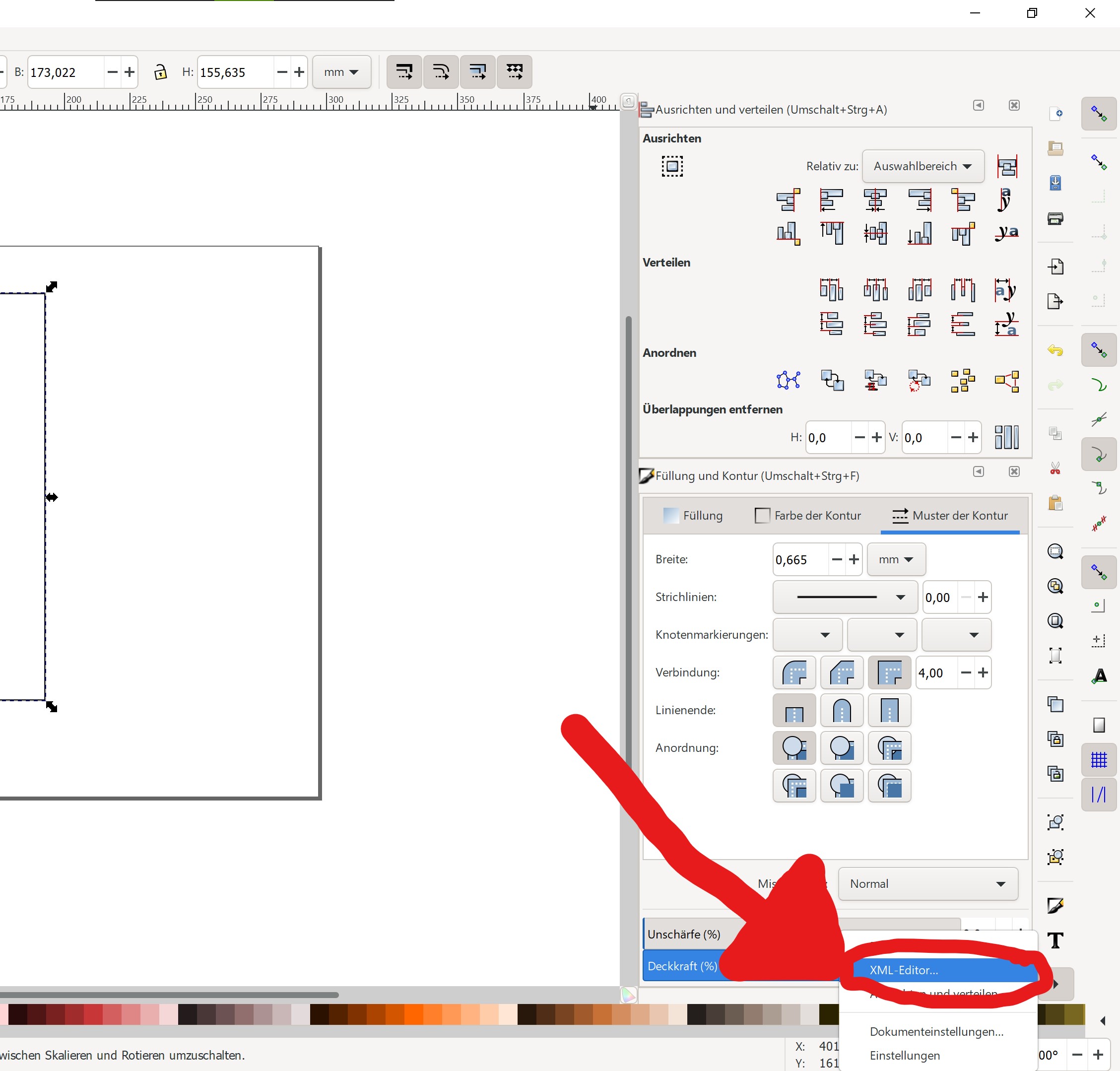
You can change the line thickness and color (depends on what you'd like to do) and then go straight to the XML-Editor. It can be found in the Menu on the side- if you can't see it, its probably hidden, like it was with me.
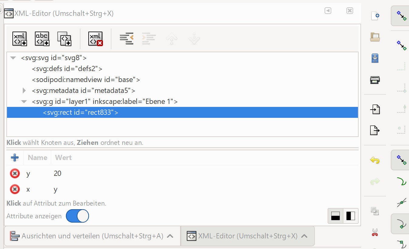
The XML-Editor is very simple and has a clear layout, which most people who don't want to do complicated stuff are thankful for. And boom! My x-side has the same dimensions as the y-side.
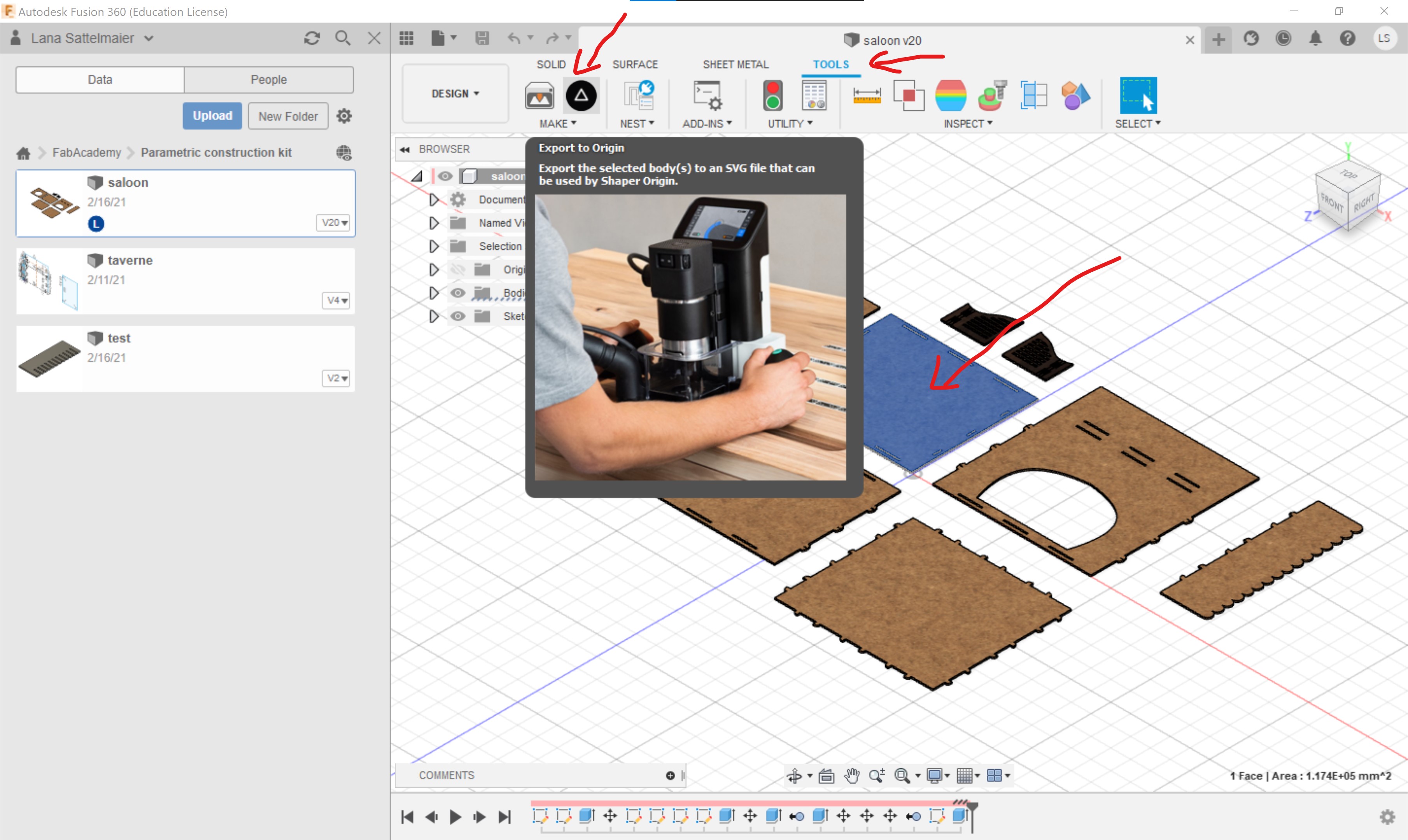
But I still prefer Fusion360, since it is easier to work with and it's possible to do it in 3D and 2D. Here I show you how to use the shaper tool add on:
First click on the object you want to save as an .svg, then you click on "tools" and on the (hopefully installed) shaper tool.
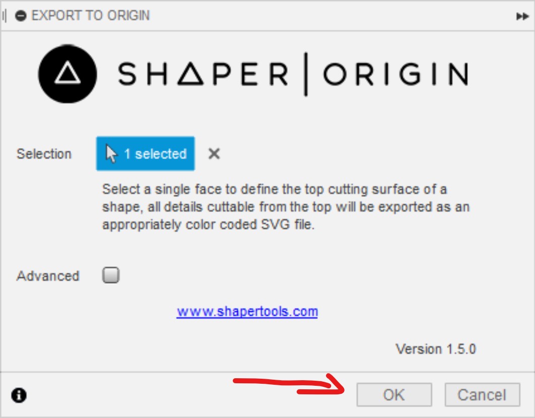
A little window should open, you can press ok and it will ask you where to save it.
If you want to have them all in one document like I did it, you can use Incscape for that.
Group Assignment
So at the moment it's hard to work together due to corona, so our group was split. Here you can see some specs about the laser:| Type of laser | CO2 |
| Power | 150W |
| Wavelenght | 10600nm |
| Resolution | 0.025mm |
| Max. engraving speed | 1000 mm/s |
| Max. cutting speed | 100 mm/s |
| Smallest engravable sign | 1mm |
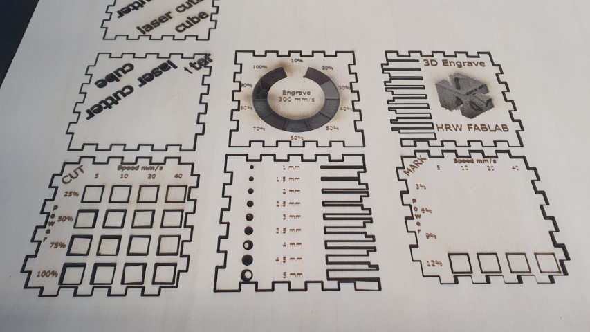
In order to define the attributes of the laser cutter, we took over a test file from Lena Hagenauer. We also did this so that our test sheets in the lab are uniform.
The exact process of the editing (which was nessecary because the big laser eats more wood away than the smaller laser which Lena used before) can be seen on Lars Mattern's Website. You can find the test file in the Downloads section. Here you can see what it looks like once it's lasered:
That's it! Have a nice day :)