Assignments
1. Principles and practices
2. Project management
3. Computer Aided design
4. Computer controlled cutting
5. Electronics production
6. 3D Scanning and printing
7. Electronics design
8. Computer controlled machining
9. Embedded programming
10. Mechanical Design
11. Input devices
12. Molding and Casting
13. Output devices
14. Networking and communications
15. Interface and application programming
16. Wildcard week
17. Applications and implications
18. Invention, intellectual property and income
19. Project development
5. Electronics production
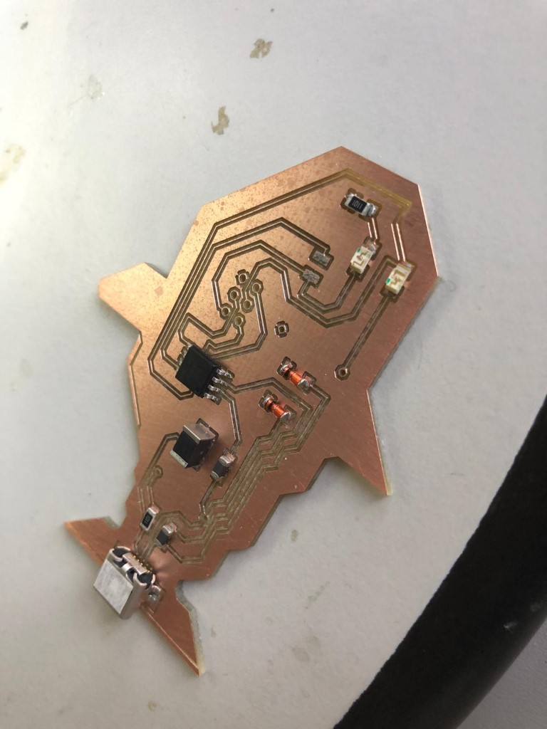
Assignment: Make an in-circuit programmer by milling and stuffing the PCB, test it, then optionally try other PCB fabrication process. Spoiler: This is the finished board: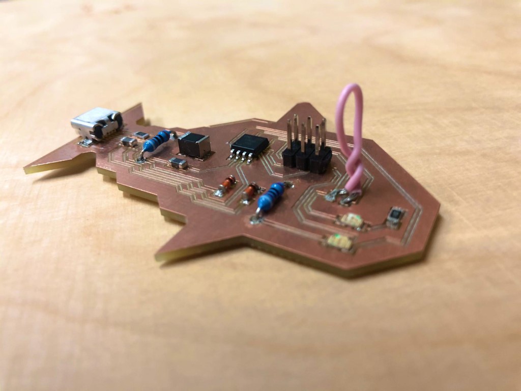
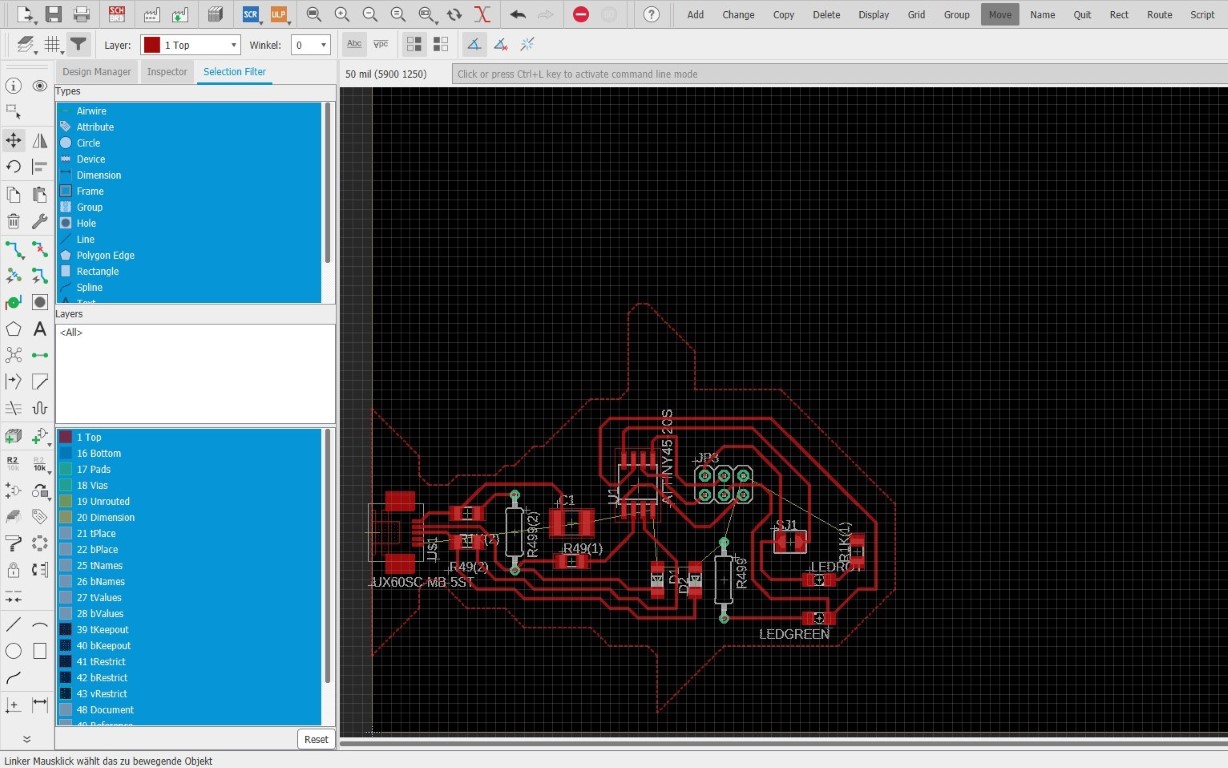
The Design
I never made a pcb in my life, so this was quite an interesting journey. I used Autodesk Eagle for the design. I know I wasn't supposed to design something yet, but at least I used the circuit diagram from Brian. The only change I did was for my special parts, I didn't have the exact parts so I improvised a little. Here are my first steps:- I installed eagle.
- Once the control panel opened after installation, I made a new project (file > new > project)
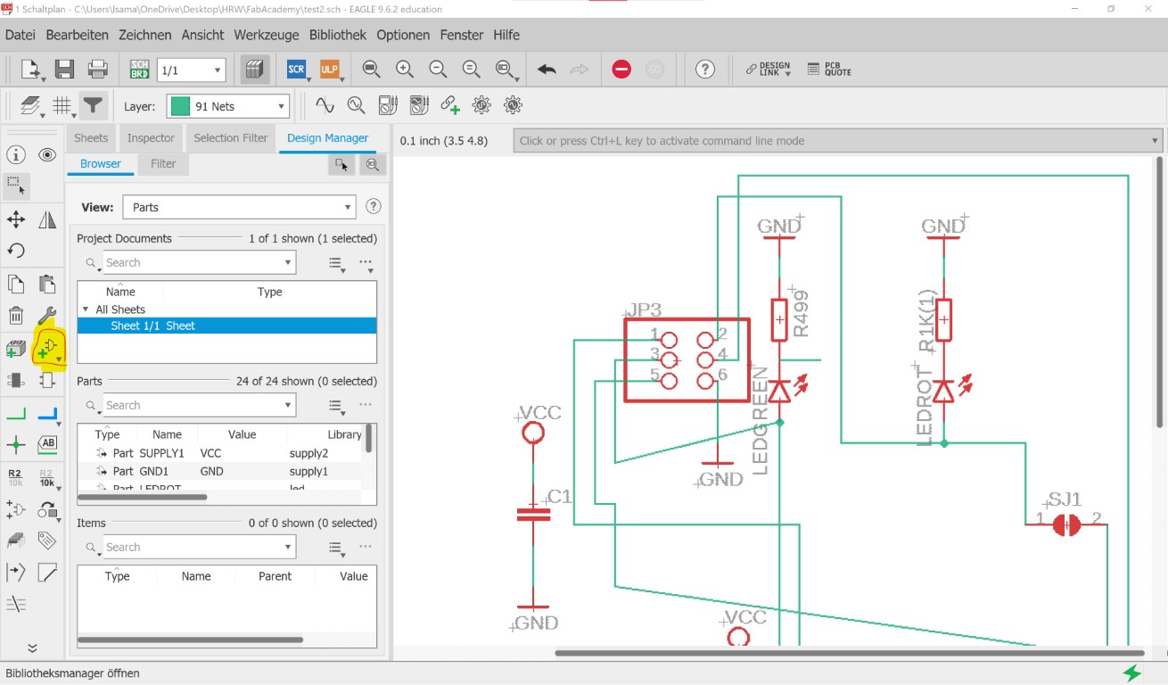
- In that project, I made a new circuit and added parts which I linked together
- After that, I saved everything and clicked on the "SCH/BRD"- button to create a board
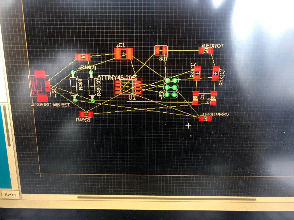
- A new window opened and the parts were scattered all over the side
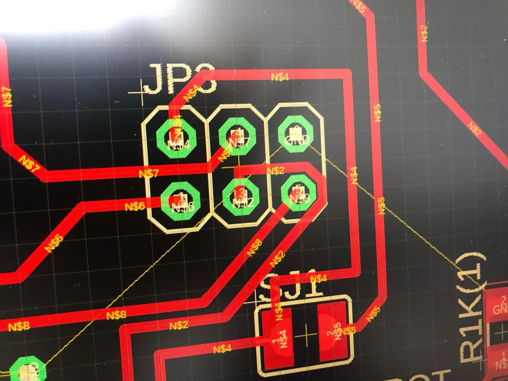
- I moved everything to the board and sorted the components
- I drew a fish with the help of the "polygon" button
- I exported everything (first turn off all irrelevant components)
And this was the first sorting iteration.
I really hope that this stuff works.
This is what it looks like all done. I chose a fish because the outline looked kind of like a fish to me :) .
Now to the export!
Milling Procedure
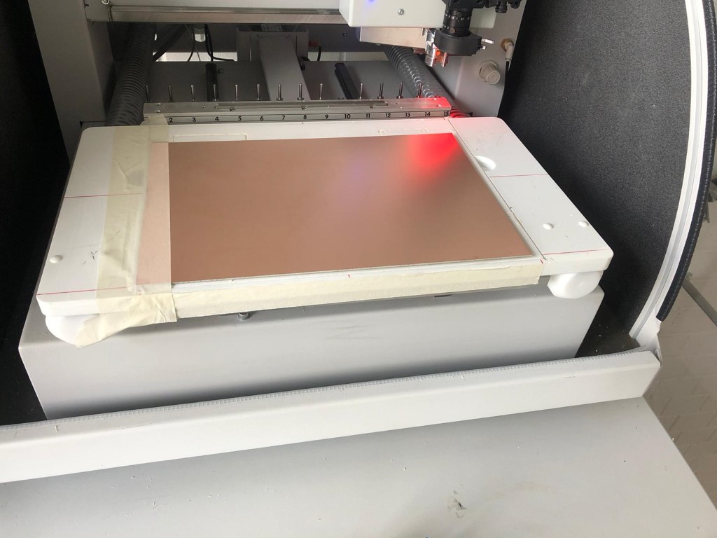
The machine's software has a setup wizard which does everything automatically. This can be really individual dependig on your material, file type and board design. But before we do that, we need to place everything in the machine.This is how the blank board is placed (stuck down with painter's tape).
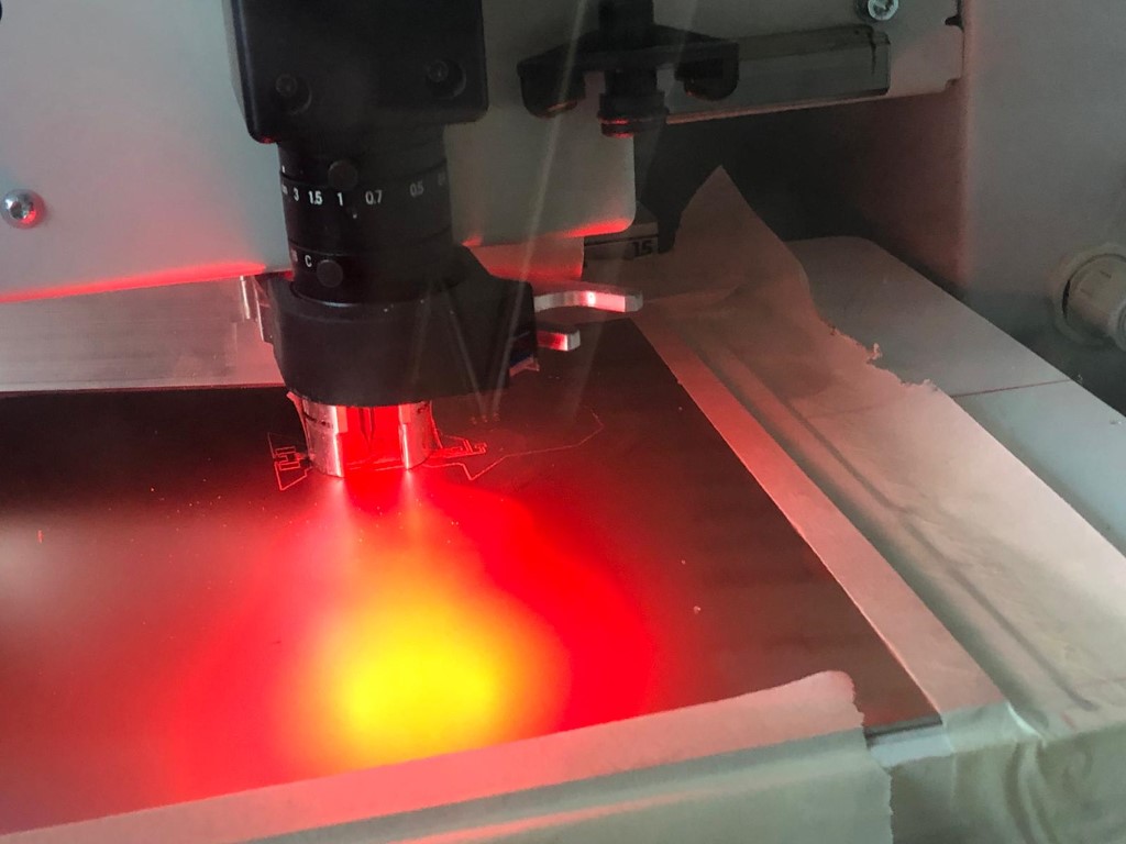
That is how it looks when it's drilled.
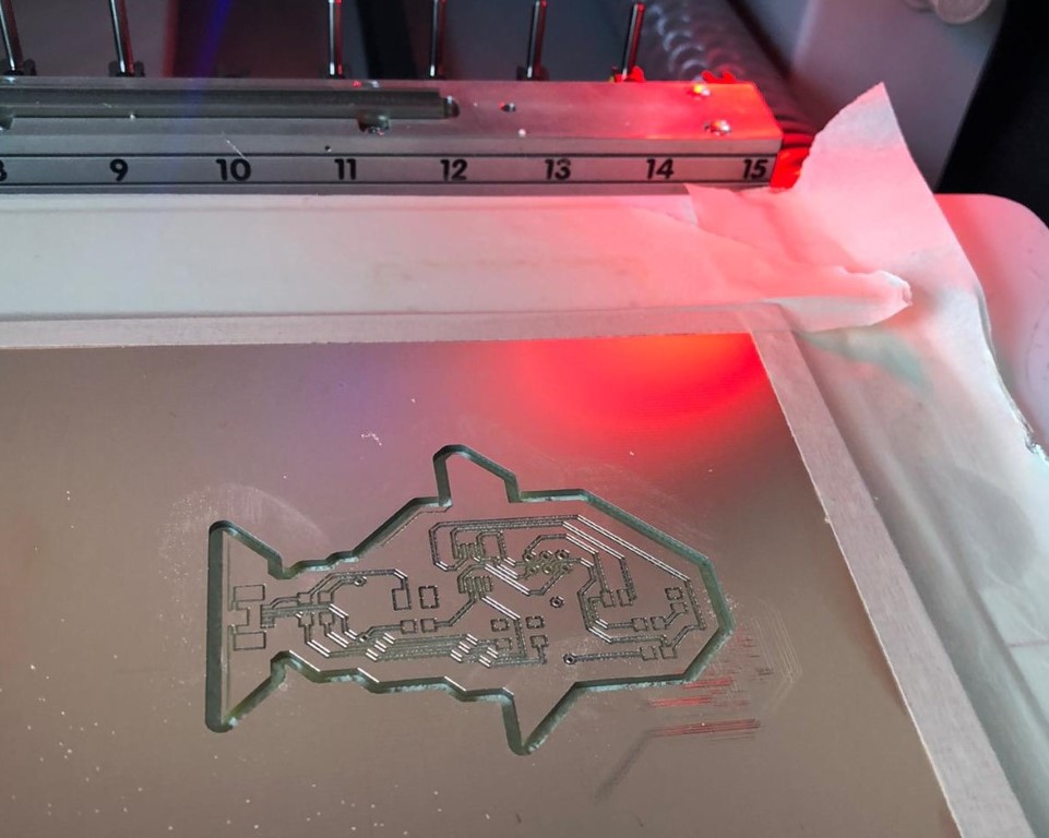
Now the fish is cut out.
After that, I put soldering paste under the microsoft on the tiny rectangles where my components need to be placed.
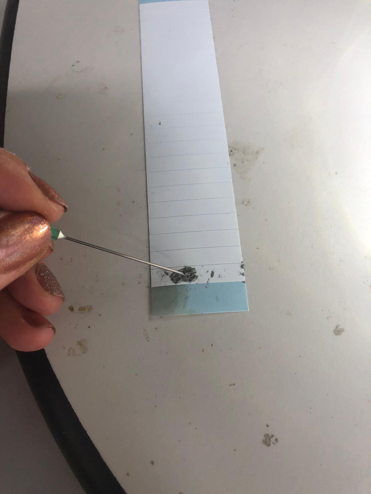
This is how I dose the soldering paste. With the needle of a syringe!
Here you can see the paste slabs on my board. After that, the parts are getting placed on top of that. I used some tweezers- it was VERY hard because I'm an extremly shaky person.
Then it comes into the oven, a Protoflow E, also from LPKF.
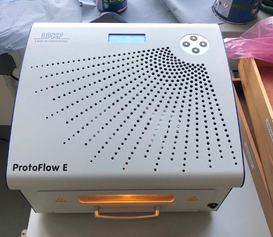
| Machine name | LPKF Protoflow E |
| Machine type | convection oven |
| Max PCB size | 160 mm x 200 mm |
| Highest possible preheat temperature/ time | 220 °C/ 999 s/td> |
| Highest possible temperature | 320 °C/ 600 s |
| Temperature stabilizing time | 320 °C/ 600 s |
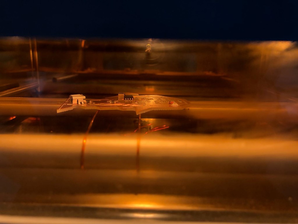
And this is how it looks in the oven (yummy, baked fish):
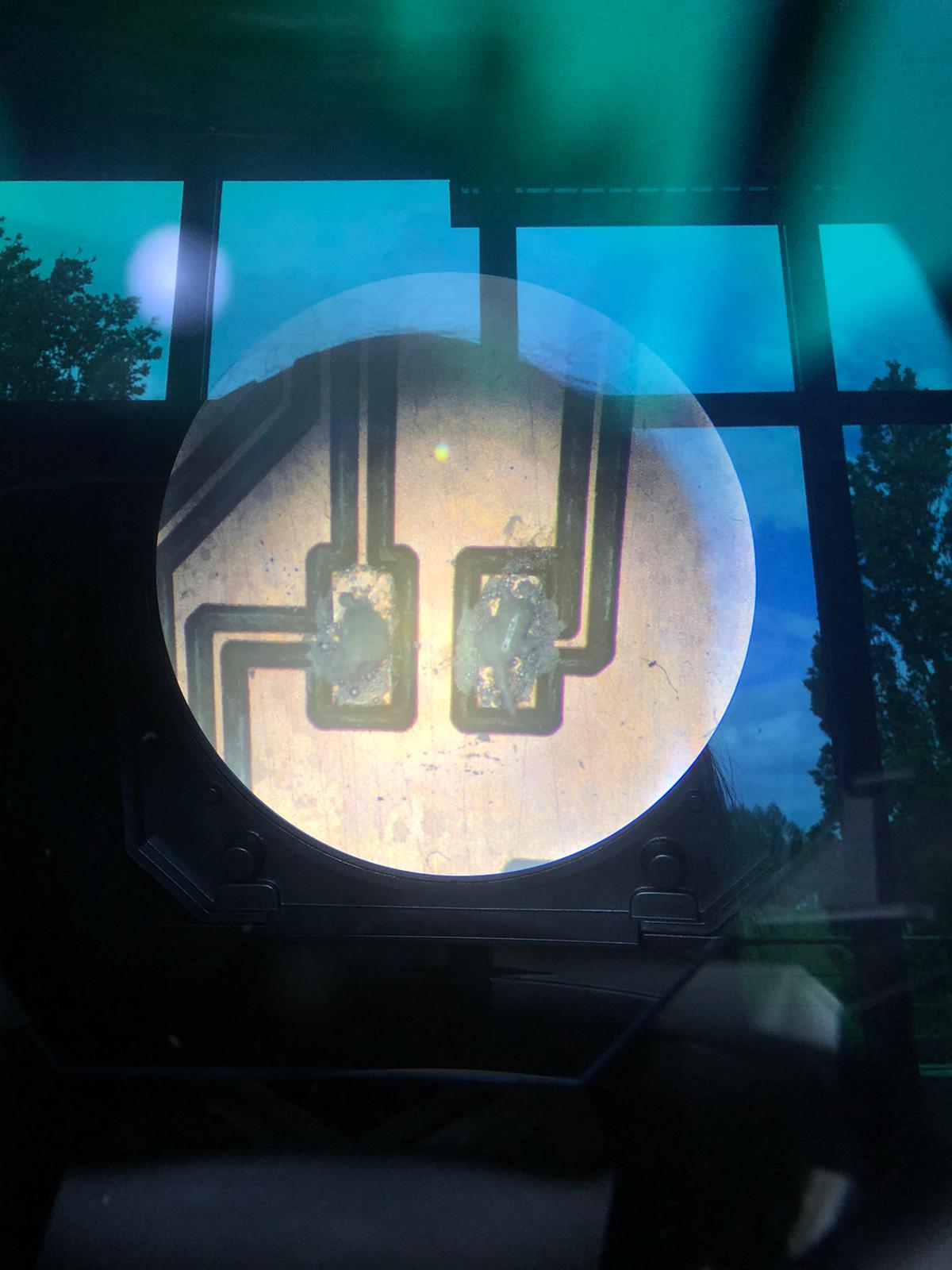
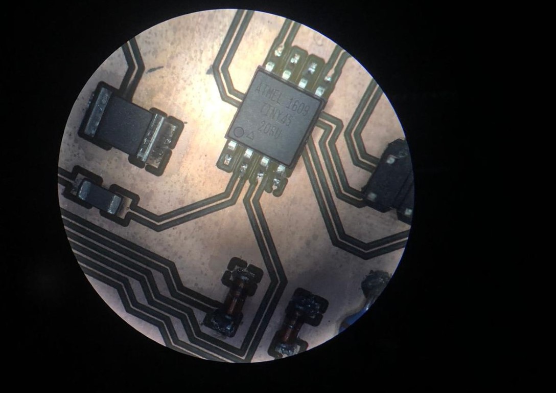
Out of the oven I realised I made a mistake. I took it too early out of the oven! But no problem- I just resoldered everything under the microscope (NEVER put a pcb more than once in the oven).
This is how the finished thing looked under the microscope.
All done!
And it even worked!
Programming
For programming, I also used Brian's tutorial. There are a few steps:- 1. Check the board for errors before doing anything. You can use a multimeter
- 2. Download GNU Make and install
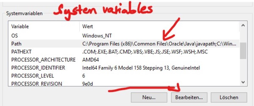
- 3. Run CMD as admin and type setx /M path "%PATH%;C:\Program Files (x86)\GnuWin32\bin" to add an environment variable to your GNU
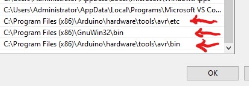
- 4. I'm using the avrdude and gnu-cc located in the C:\Program Files (x86)\Arduino\hardware\tools\avr\bin directory, so I don't need to install it manually. Just set the environment variables like this (run command prompt as admin) setx /M path "%PATH%;C:\Program Files (x86)\Arduino\hardware\tools\avr\bin" and this setx /M path "%PATH%;C:\Program Files (x86)\Arduino\hardware\tools\avr\etc". If this doesn't work, you can always add them manually
- Close the command prompt and reopen it. Type make to test what you did. If you get an error, check your environment variables manually.
- 5. Download the flashing software here
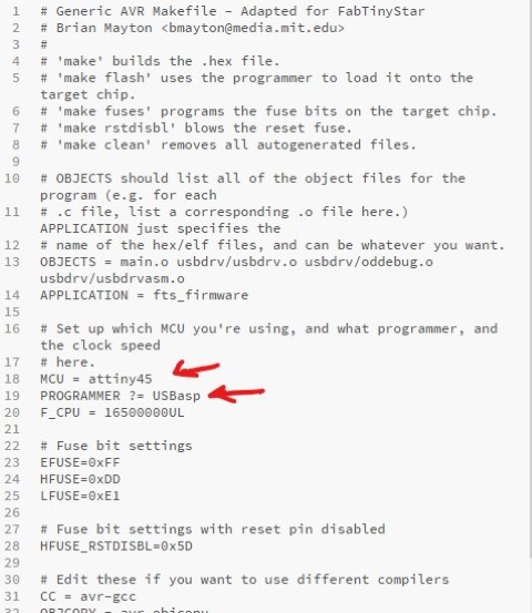
- 6. Unzip it and edit the Makefile. You can open it with a random text editor
- 6.1 I changed the line PROGRAMMER ?= usbtiny to PROGRAMMER ?= usbasp, because I used an usbasp
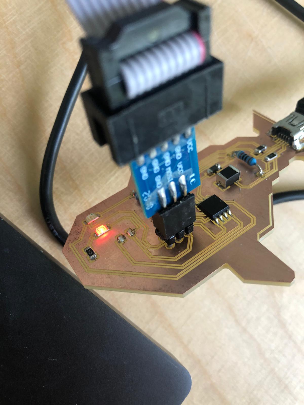
- 7. Plug your board to the programmer and connect it to your pc- the led should be red
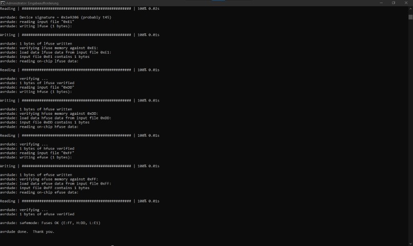
- 8. Now run make flash and make fuses, if make flash worked. If it didn't work, check your ISP connections. DON'T CLOSE THE CMD WINDOW
- 9. Disconnect the board and the programmer from the PC and plug the board via USB in
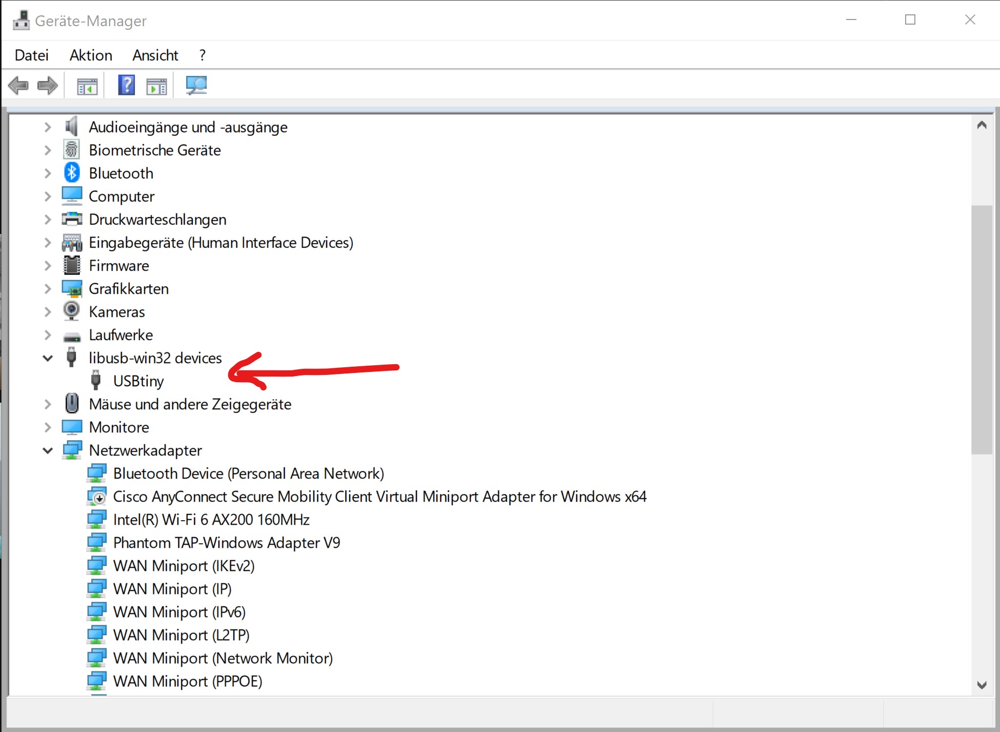
- 10. If the USB is recognized by the pc (check the device manager to be sure), then everything is okay
- 11. Disconnect the board again and reconnect it using the programmer again
- 12. Run make rstdisbl in the console to make the attiny overwriting-proof by disabling the fuses
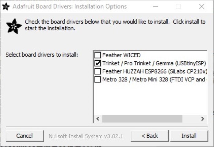
- 13. Plug your device in again and run the driver manager. Download the Adafruit driver installer here
- 14. Done!
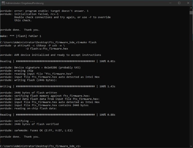
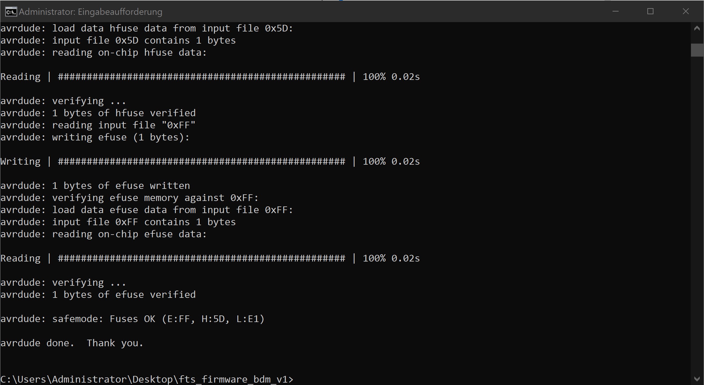
 This is how it should look like when you run "Make flash".
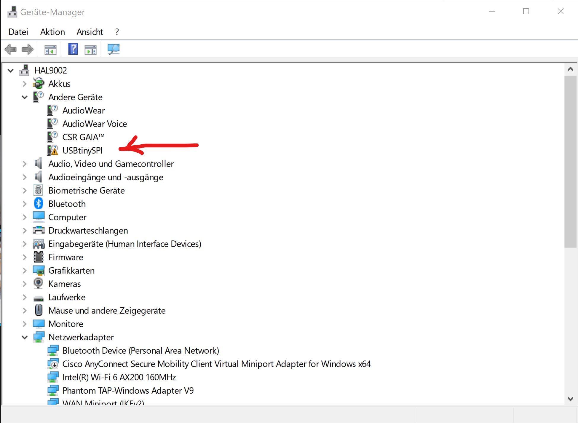
Problems I had
I missed a trace and wondered why my Attiny doesn't get power from the USB port-oh well I corrected it so you shouldn't worry if you like to redo my fishy.I also soldered the diode the wrong way so if your PC doesn't recognize your board, please consider this.
Group Assignment
We have a nice lil' milling machine from LPKF Laser & Electronics and it just works like a charm. It can mill blanks and is able to adjust the milling width automatically. It also has an optical edge recognition (camera) to create 2-sided boards.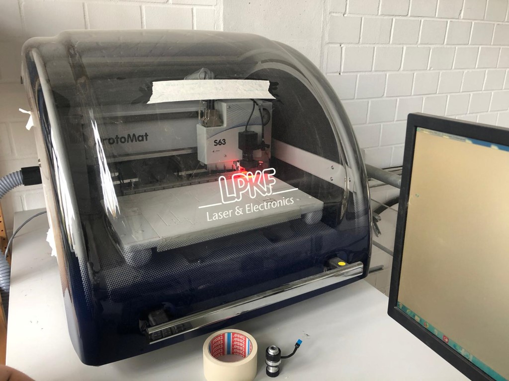
| Machine name | LPKF 63 |
| Workspace | 229 mm x 305 mm x 35/22 mm |
| Automated tools | 15 |
| Smallest millable structure | 100 µm |
| Milling and drilling spindle | 60.000 rpm |
Linetest
We used the linetest from Lena. This is how it turned out:First we made a mistake and reversed it, this is how it looked:
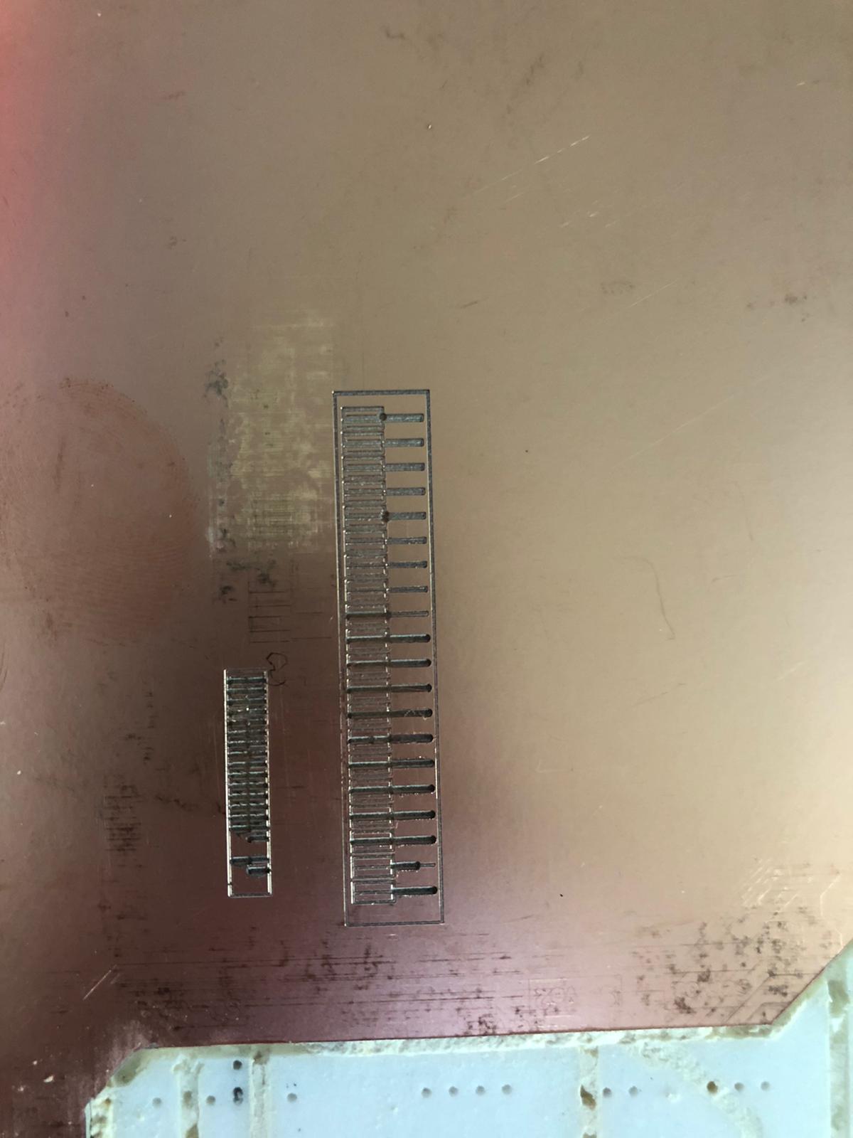
Then we finally made it:

This test starts at a thickness of 0.02mm and and it goes up in 0.2mm steps to 0.04mm.
| 0.02mm | The milling was too strong, the line doesn't conduct anymore. The other lines are all conductive which means that we could produce conductors up to 0.04mm thickness. However, 0.04mm is too fine and could break quickly during soldering. That's why we will work with a thickness beween 0.1 to 0.3mm. |
| Up to 0.4mm | With the upper partition of the material we get acceptable results from 0.02mm which is our thinnest milling head. For the seperation between the tracks we'll choose a thickness of at least 0.2, since this matches the next larger cutter, which is much more stable. |