Assignments
1. Principles and practices
2. Project management
3. Computer Aided design
4. Computer controlled cutting
5. Electronics production
6. 3D Scanning and printing
7. Electronics design
8. Computer controlled machining
9. Embedded programming
10. Mechanical Design
11. Input devices
12. Molding and Casting
13. Output devices
14. Networking and communications
15. Interface and application programming
16. Wildcard week
17. Applications and implications
18. Invention, intellectual property and income
19. Project development
9. Embedded programming
Assignment:Group assignment:
Compare the performance and development workflows for different microcontroller families
Document your work (in a group or individually)
Individual assignment:
Read the datasheet for the microcontroller you are programming
Program the board you have made to do something, with as many different programming languages and programming environments as possible.
Prologue
(Look for Week 7 if you're confused.)
Planning
Since I used the ATmega328p in the Electronics Design Week, I use its Datasheet this week. The Atmel® ATmega328P is a low-power CMOS 8-bit microcontroller based on the AVR® enhanced RISC architecture. By executing powerful instructions in a single clock cycle, the ATmega328P achieves throughputs approaching 1MIPS per MHz allowing the system designer to optimize power consumption versus processing speed. Now let's look at some specs:| Chip Type | ATMEL ATmega328p |
| Operating voltage | 2.7V - 5.5V |
| Low power consumption |
|
| EEPROM | 1K byte |
| Internal SRAM | 2K bytes |
| Flash memory | 32K bytes |
| Write/erase cycles | 10,000 flash/100,000 EEPROM |
Here you can see the pin placing:
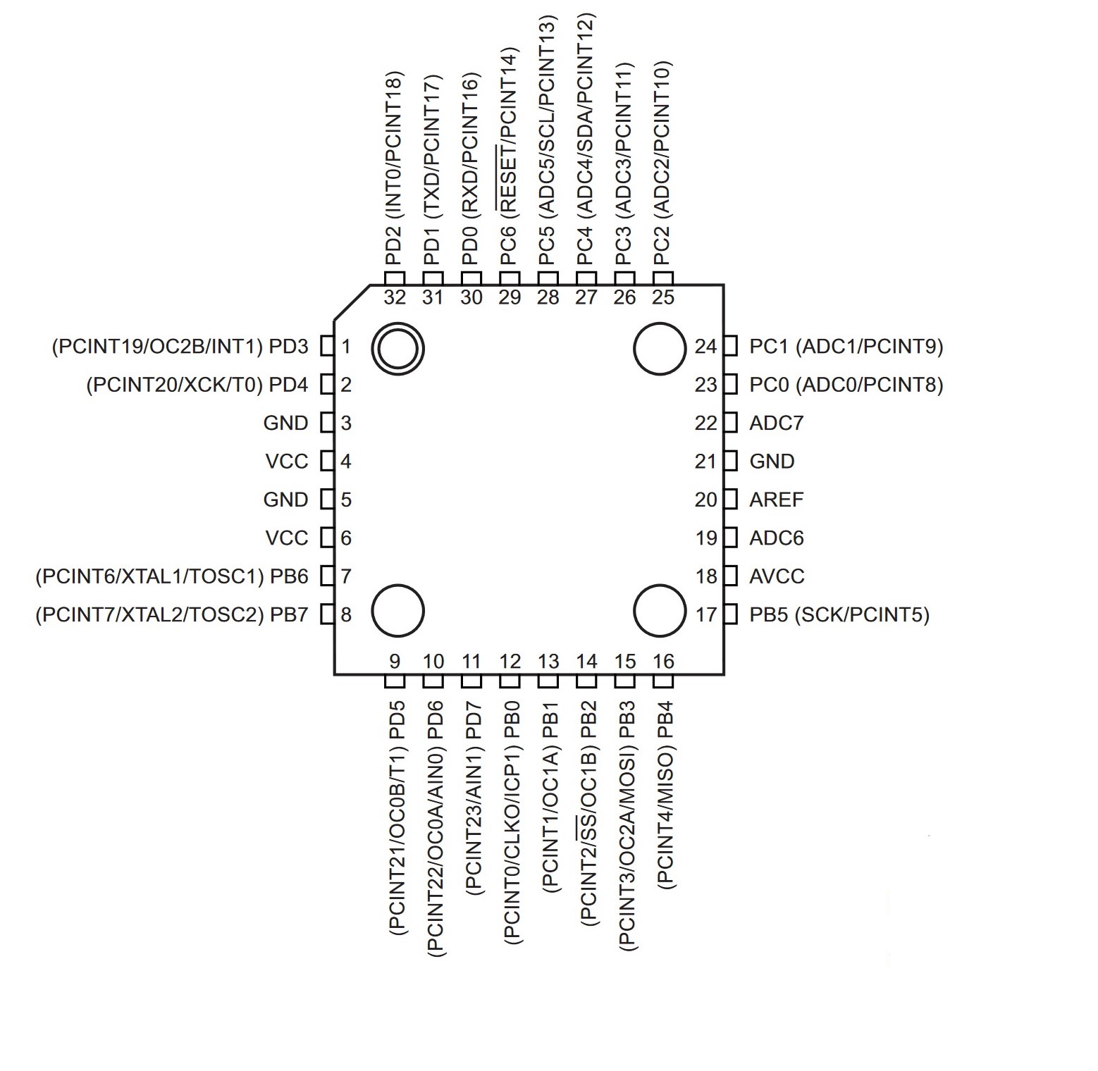
It is important to know which pins are available since we have to "talk to them". As you can see there are a few PB's, PC's and PD's. Those are so called ports.
Port B is a bidirectional 8-bit I/O port with internal pull-up resistors (selected for each bit). Port B output buffers have balanced driver characteristics with high sink and source capability. As inputs, Port B pins pulled low externally become current sources when the pull-up resistors are enabled. Ports that belong to Port B: PB0 - PB7 (8 Bit).
Port C is a 7-bit bi-directional I/O port with internal pull-up resistors (selected for each bit). The PC5..0 output buffers have symmetrical drive characteristics with both high sink and source capability. As inputs, Port C pins that are externally pulled low will source current if the pull-up resistors are activated. The port C pins are tri-stated when a reset condition becomes active, even if the clock is not running. If the RSTDISBL fuse is programmed, PC6 is used as an input pin. If the RSTDISBL fuse is unprogrammed, PC6 is used as a reset input.Ports that belong to Port C: PC0 - PC6.
Port D is an 8-bit bi-directional I/O port with internal pull-up resistors (selected for each bit). The port D output buffers have symmetrical drive characteristics with both high sink and source capability. As inputs, port D pins that are externally pulled low will source current if the pull-up resistors are activated. Ports that belong to Port D: PD0 - PD7.
Programming
As you can see in Week 7, programming was a real pain, since nothing seemed to work and nobody was able to help me. That's why I made a new board this week in hopes that this will work now. I documented in Week 7 that it works now!To program it, I just left the programmer plugged in, as before.
Testing
Now onto something fun: NEOPIXELS!We can do everything with them! They are dimmable, can be different colors and I can make them blink! Now I just need to plan the layout:
And heeeere we go:
Programming the blink in C
It is possible to fully program in C using the Arduino IDE. Alternatively it is also possible to use Visual Studio Code together with the Platform IO Extension.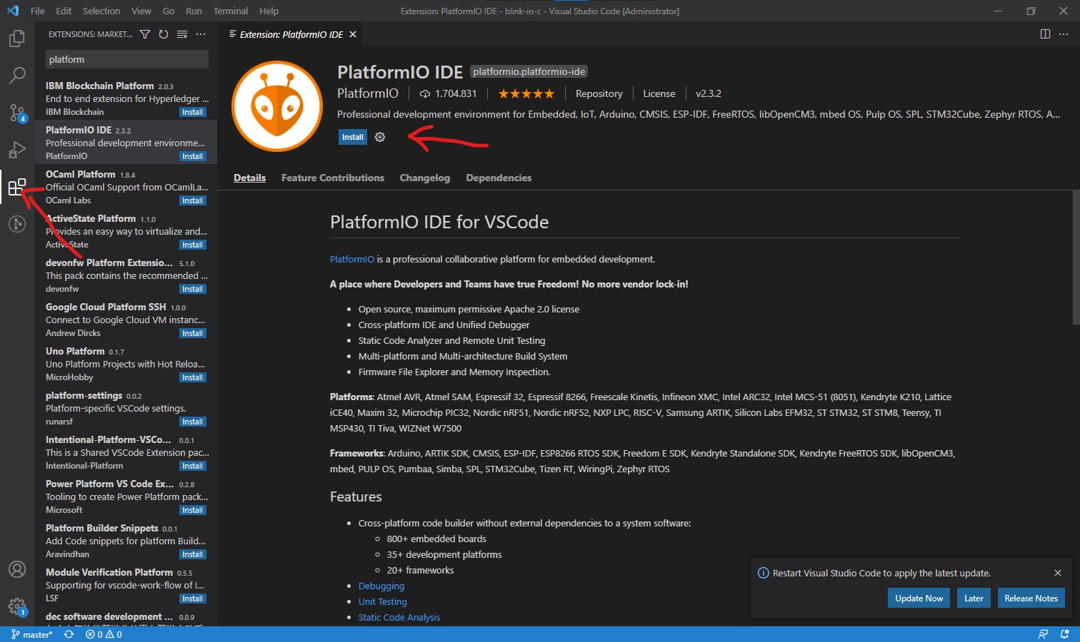
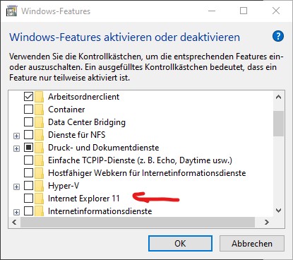
Just get your PlatformIO extension from the extension menu and hit install. Deactivate your Internet Explorer in Windows Features or else PlatformIO wont be able to load!
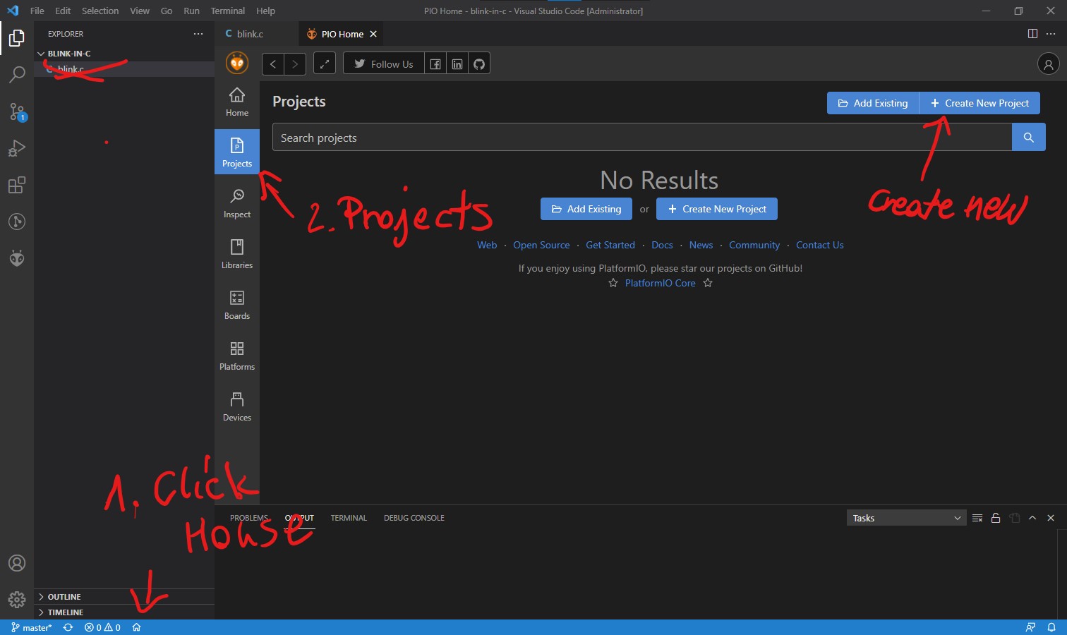
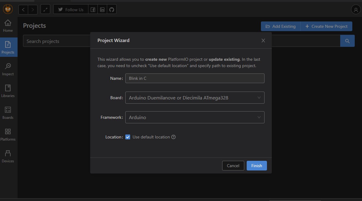
Restart VSC and you'll find the house (on 1) in the bar down below. Click it. After that you can create a new project.
Here you can select your board, I used the Arduino Duemilanove because that's what I flashed on my ATMega328p. You can use what you like.
It will create this nice tree for you.
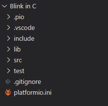
The main CPP can be found in the src folder.
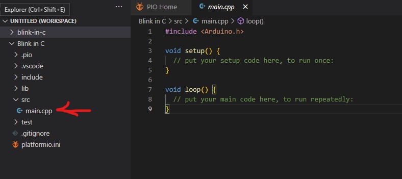
Now simply put your C code into the file. I used PB5 because my onboard led is connected to it. Usual Arduinos should be the same.
With the arrow you can upload it to your board.
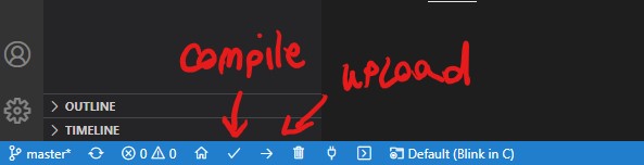
And it should look like this down below. If it's not working, check your vscode settings.json, some VSC versions have the problem that "task.autoDetect": "on" is missing.
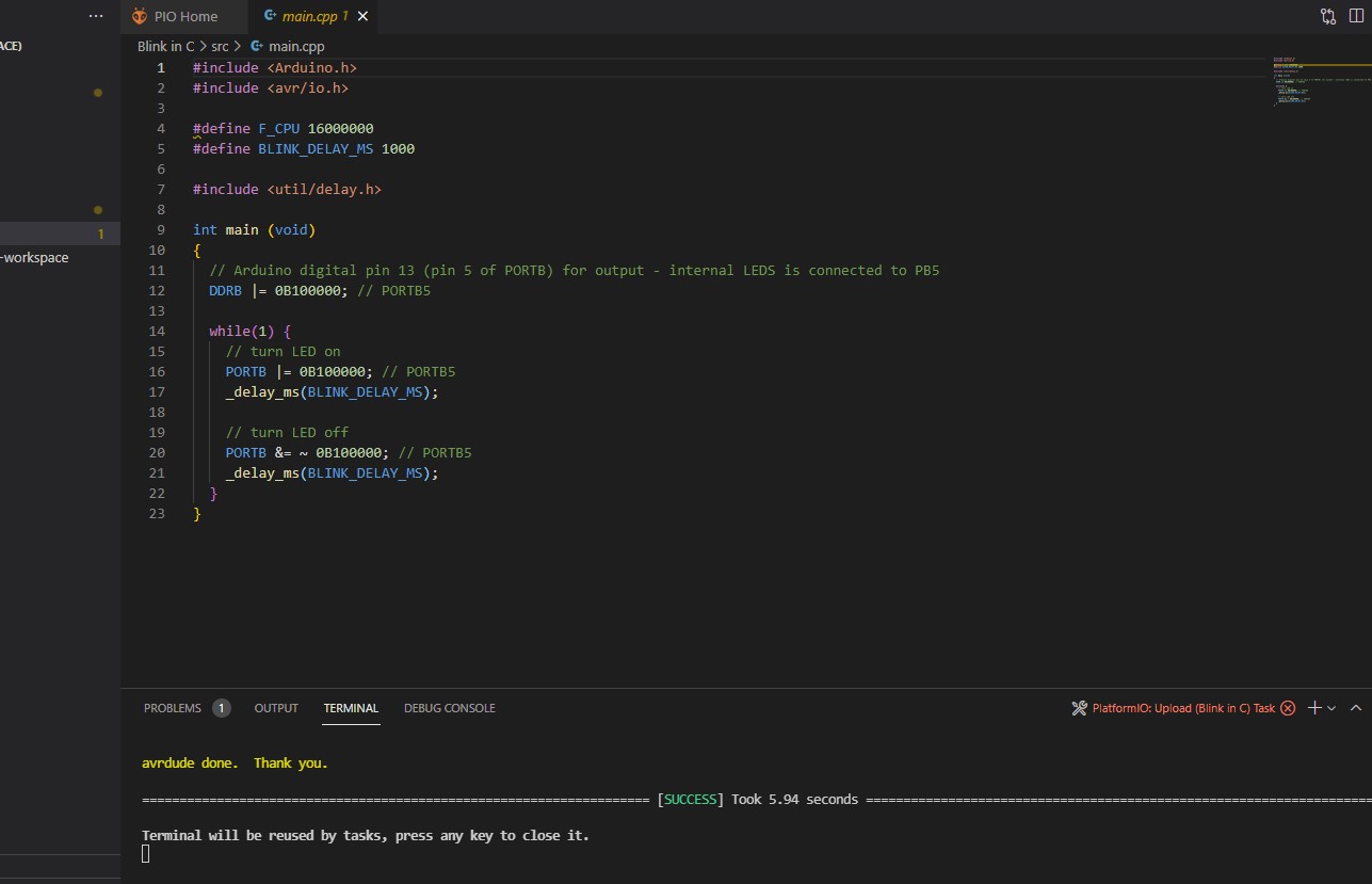
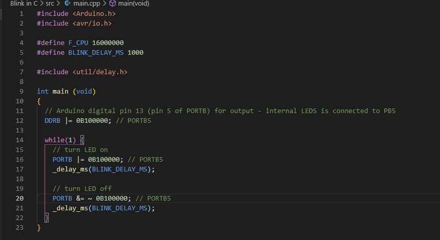
I know this type of code is hard to get so here ya go:
  #include <Arduino.h>
    #include <avr/io.h>

    #define F_CPU 16000000
    #define BLINK_DELAY_MS 1000

    #include <util/delay.h>

    int main (void)
    {
      // Arduino digital pin 13 (pin 5 of PORTB) for output - internal LEDS is connected to PB5
      DDRB |= 0B100000; // PORTB5

      while(1) {
        // turn LED on
        PORTB |= 0B100000; // PORTB5
        _delay_ms(BLINK_DELAY_MS);

        // turn LED off
        PORTB &= ~ 0B100000; // PORTB5
        _delay_ms(BLINK_DELAY_MS);
      }
    }
The board is blinking again!
Group Assignment
For the group assignment I decided to programm an ESP8266 because I had it laying around here. It is also possible to programm it either in the Arduino IDE or in Platform IO. For the Arduino IDE however, it is necessary to install some libraries to be able to program the board.Sooo onto step 1:
Put this nice line https://arduino.esp8266.com/stable/package_esp8266com_index.json into your Arduino preferences.
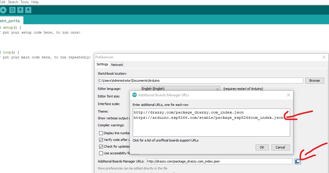
Look in tools > board> board manager for the 8266 and hit install.
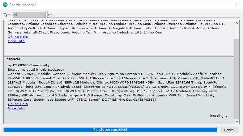
I chose "Generic ESP8285 Module" because this is what I had. You can find your description in the datasheet of your ESP.
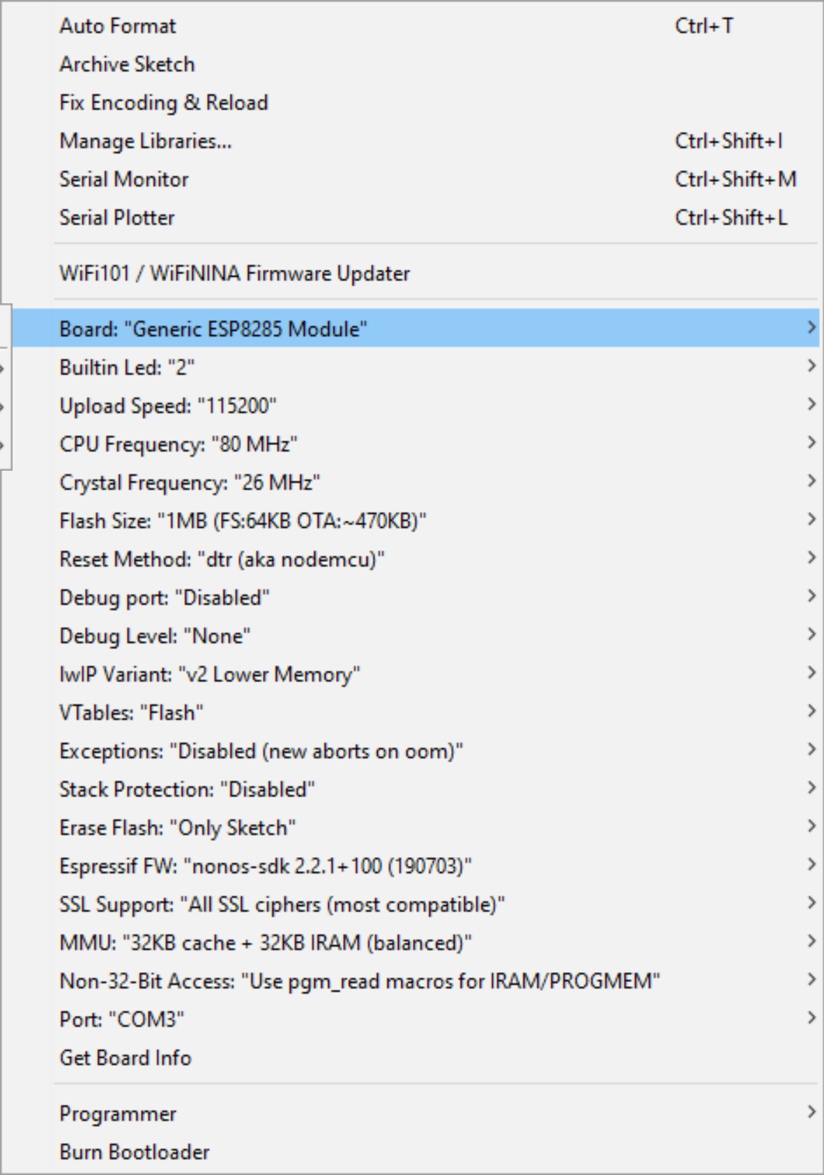
Now before booting, check this before:
I used a usb to ttl adapter, I needed to connect the following to be able to program it:
- TTL --- ESP
- 3.3V --- 3V3
- GND --- GND
- GND --- IO (I made an y-adapter so I can connect both to gnd)
- RXD --- TX
- TXD --- RX
Oh and this was the code. Very similar to the code for a generic Arduino Uno.
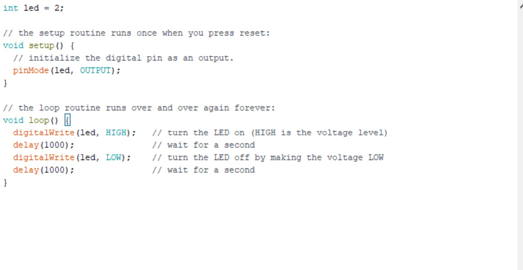
Here goes the copypastabele code:
  int led = 2;

// the setup routine runs once when you press reset:
void setup() {
  // initialize the digital pin as an output.
  pinMode(led, OUTPUT);
}

// the loop routine runs over and over again forever:
void loop() {
  digitalWrite(led, HIGH);   // turn the LED on (HIGH is the voltage level)
  delay(1000);               // wait for a second
  digitalWrite(led, LOW);    // turn the LED off by making the voltage LOW
  delay(1000);               // wait for a second
}
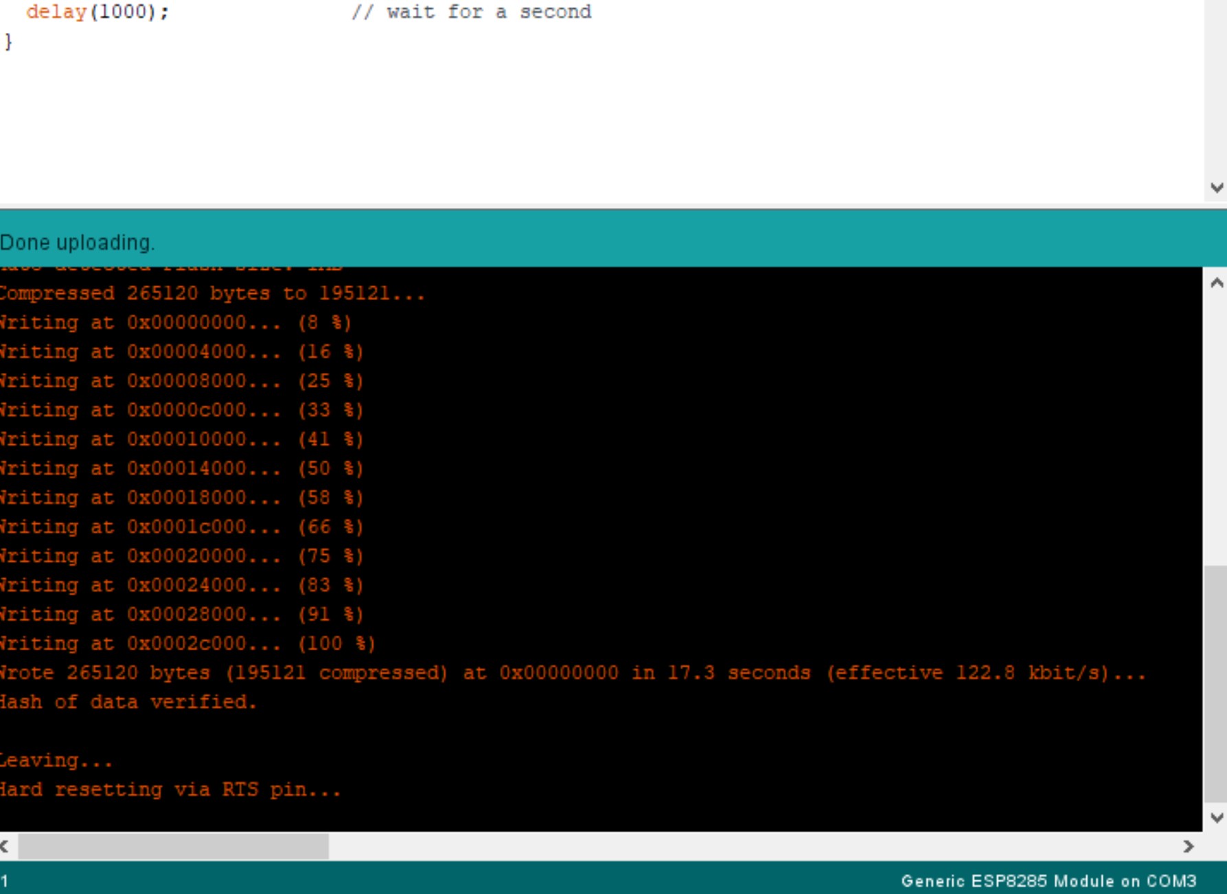
NOW DISCONNECT THE USB ADAPTER. The reason for that is because it will go in program mode if you leave it in or plug it again. So to test if the blinking is really working, you just need to unplug all of the cables from the esp and only leave vcc and gnd. Then you can plug it back into the pc and you should see your blink.
It is a little easier to program an ATMega328p, since you dont need to replug cables before testing and there is a bigger community for this. When I first had problems with my esp module, it was hard to find a solution for this specific board. My ESP8266 is actually an ESP8285 which is, again, basically an ESP with integrated flash storage.