Assignments
1. Principles and practices
2. Project management
3. Computer Aided design
4. Computer controlled cutting
5. Electronics production
6. 3D Scanning and printing
7. Electronics design
8. Computer controlled machining
9. Embedded programming
10. Mechanical Design
11. Input devices
12. Molding and Casting
13. Output devices
14. Networking and communications
15. Interface and application programming
16. Wildcard week
17. Applications and implications
18. Invention, intellectual property and income
19. Project development
8. Computer controlled machining
Assignment:Group assignment:
Test runout, alignment, speeds, feeds, and toolpaths for your machine Document your work (in a group or individually) Individual assignment:
Make (design+mill+assemble) something BIG! Spoiler: My rocking dinosaur.
Group Assignment
So since I knew what my design should be, I needed to test how much wood the mill is eating away. I started with this simple design: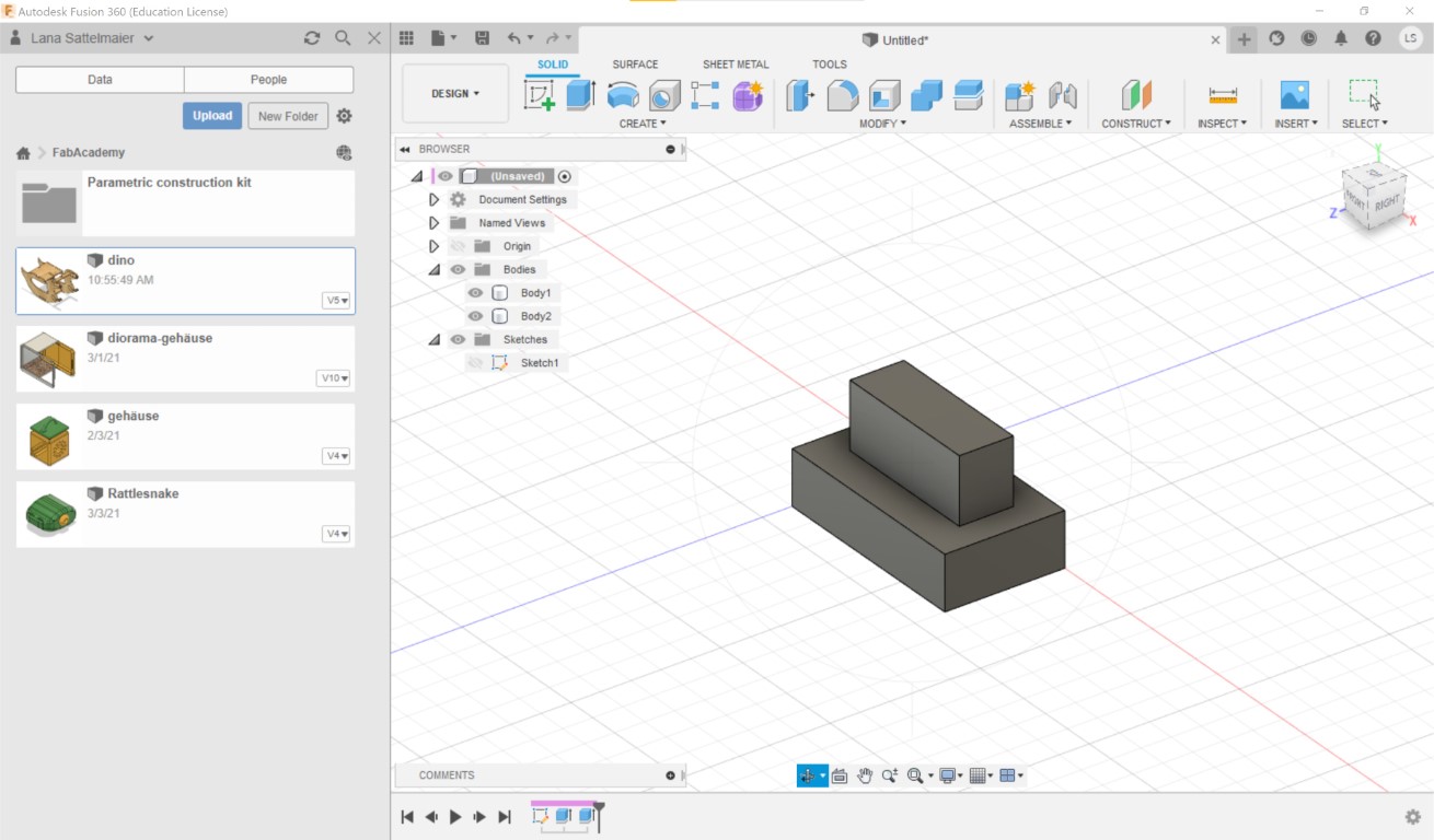
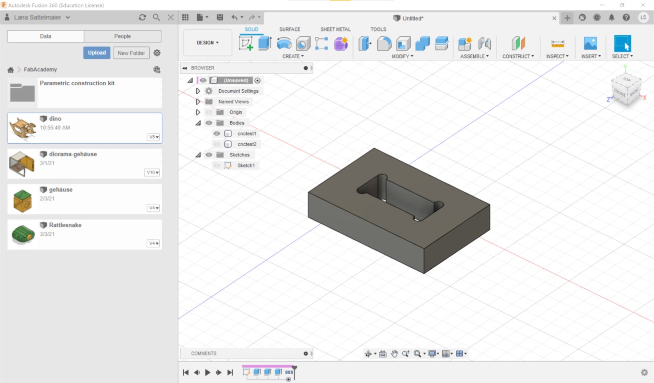
This obviously wouldn't work with a mill since mills can't cut corners like lasercutters can. We need to spare the corners so the edges will fit. I did that with Nifty Dogbone.
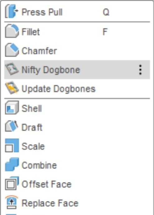
Its a great extension for that kind of stuff! You can choose in the menu what kind of corners you'd like (since they are later visible).
Now I'll test it out! This is our CNC mill, we're using the Longmill CNC:
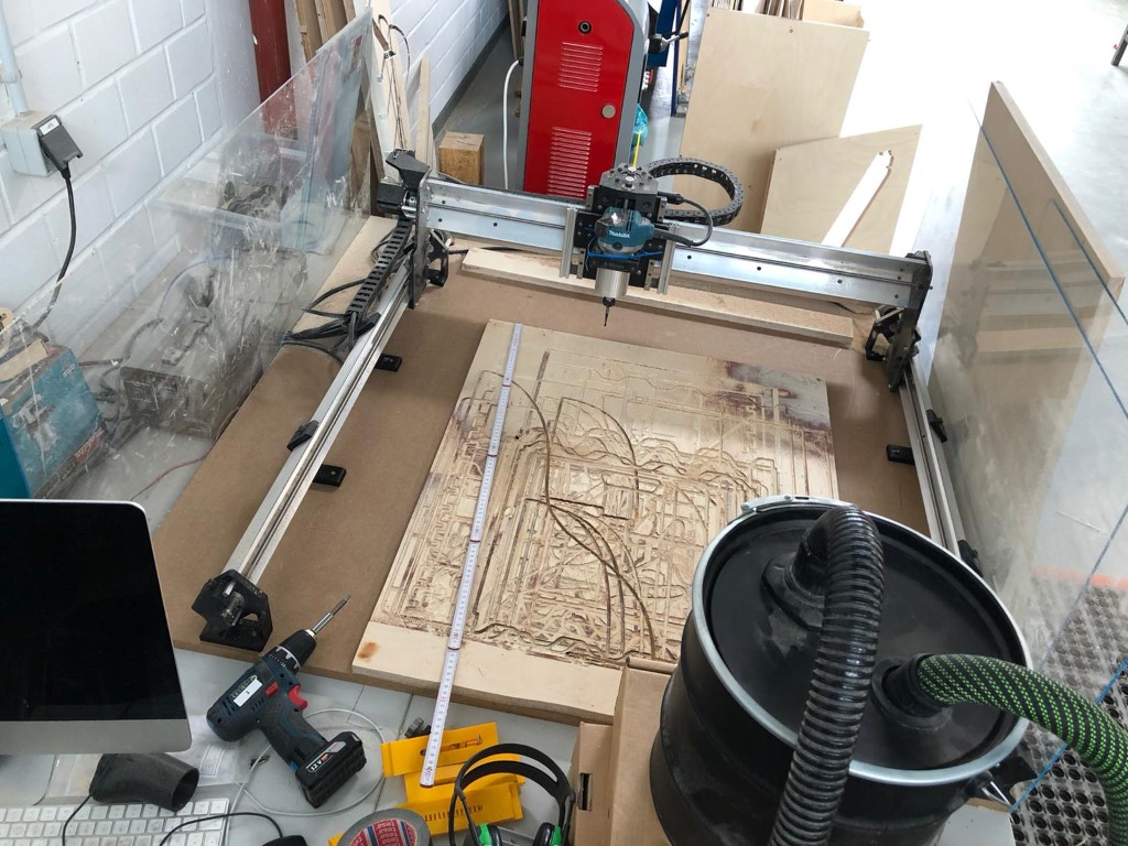
| Machine name | LongMill Benchtop CNC |
| Cutting area | 30x30" (~76x76cm) |
| Router size | 65mm (Makita Router) |
| Z-axis travel | 113mm |
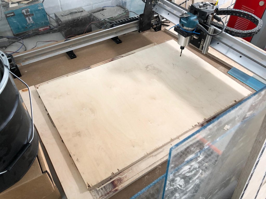
The board under it is there to protect the board that came with the mill. So I'm starting with a fresh piece of wood in my desired thickness (18mm, since my dinosaurs should be sturdy).
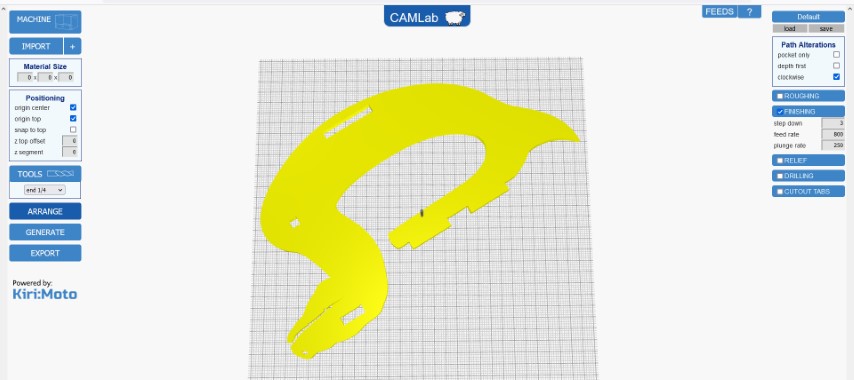
Perfect! Now I got to Sienci's CAMLab to prepare my STL. The machine cannot read STL directly so we have to slice it to make it a gcode. We can import our STL file and rotate it as we like.
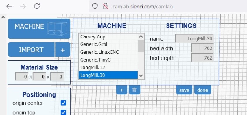
Here we can select our LongMill machine.
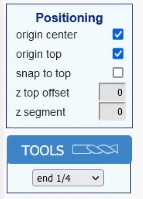
For positioning you can do as you like. I like to chose "origin top" and "snap to top" - I disselected "origin center". I ignored the material size.
Now all we have to do is to generate and export it. You can name and download it afterwards.
To bring this to our CNC we need to open the GUI for it. We use the Universal G-Code Sender for this.
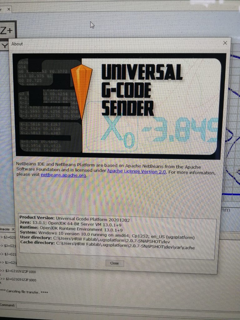
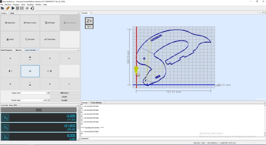
This is what the software looks like.
Here's what to do before milling:
- Move the Z-axis to the top if it's down.
- Move the x&y-axes to the side.
- Place your board which you want to cut onto the cutting area and fix it.
- Move all of the axes to the zero point of your file (you can see this in CAMLab)- keep space between the drill and the board.
- Turn on the router.
- SLOWLY (!) move the Z-axis down until it's touching the board.
- Now click on "reset zero" and voila! Your zero point fits perfectly.
- Now you can start the job.
I like the way the console talks to me (it's nice, you can see errors in realtime).
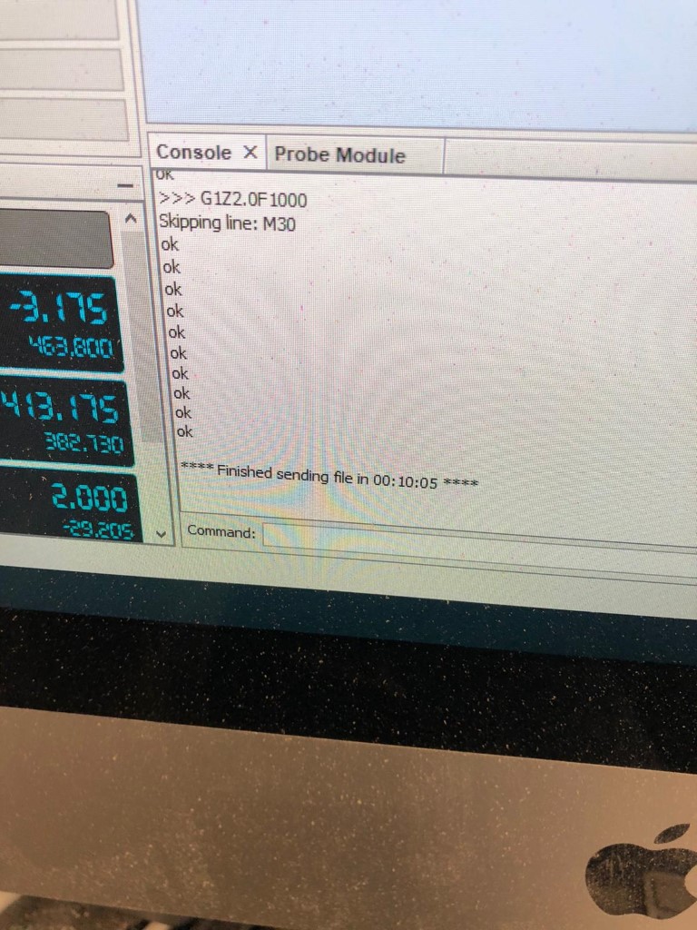
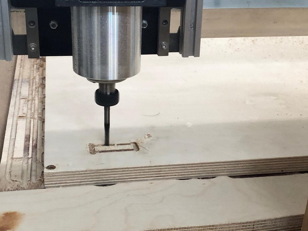
Aaand it doesn't fit. It looks like the hole needs to be bigger (4mm).
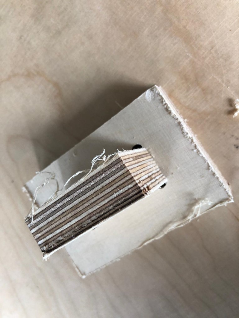
With that knowledge, I'm starting my design.
Design
So this was my first design: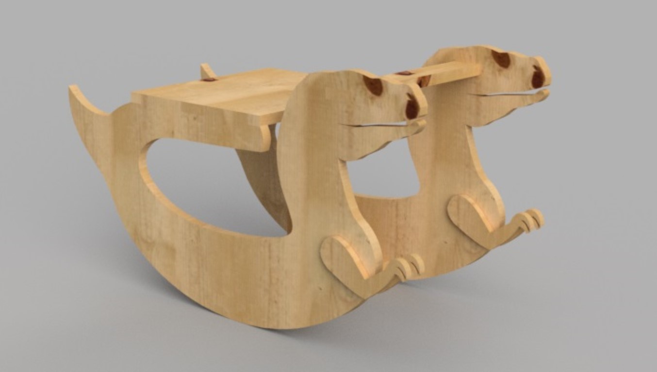
Then I realized that there is no way this thing would stay together. That's why I chose to do some bolts:
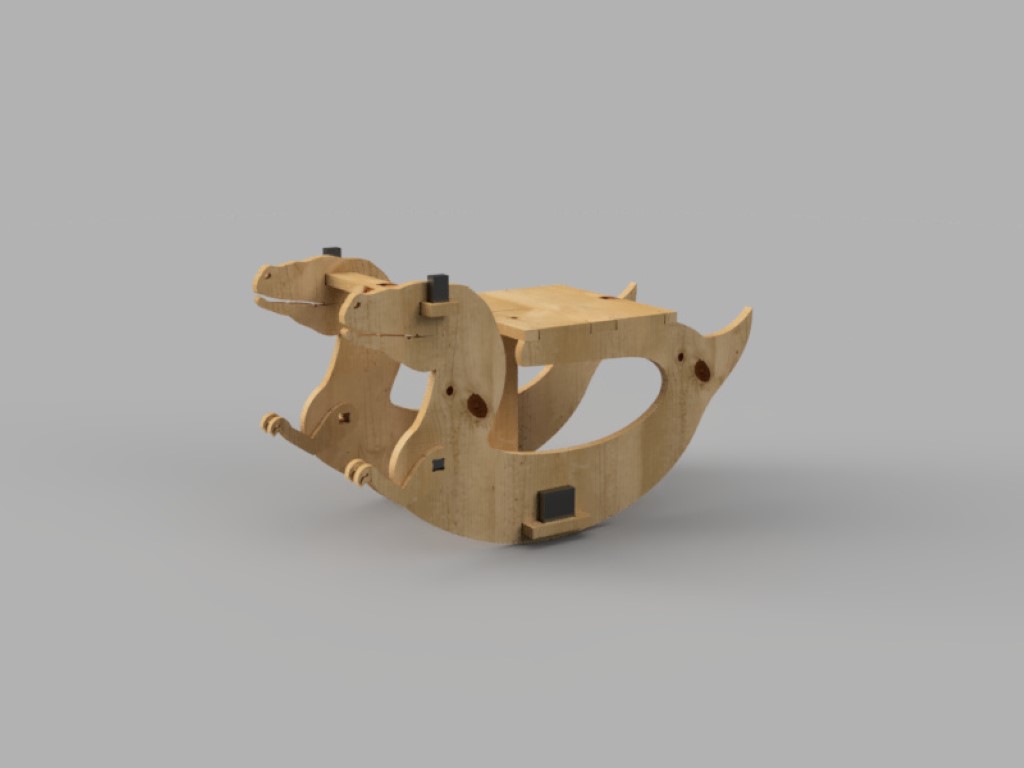
As you can see, the bolts are keeping those cuties together.
Milling Process
The milling process was fairly incomplicated and I actually had a little bit fun. It just takes soooo long.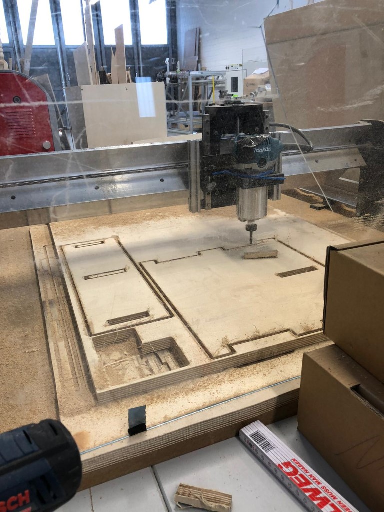
The detailed process is explained above, in the Group Assignment.
Assembling
The assembling was easy. Just stick everything together and done! It only stays together once it's complete. Otherwise it will fall apart.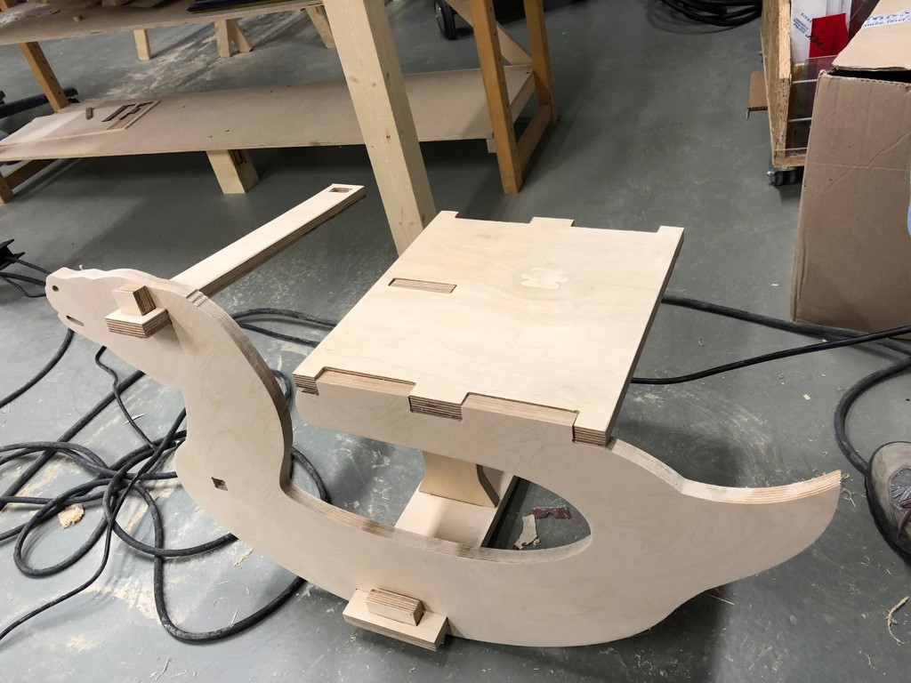
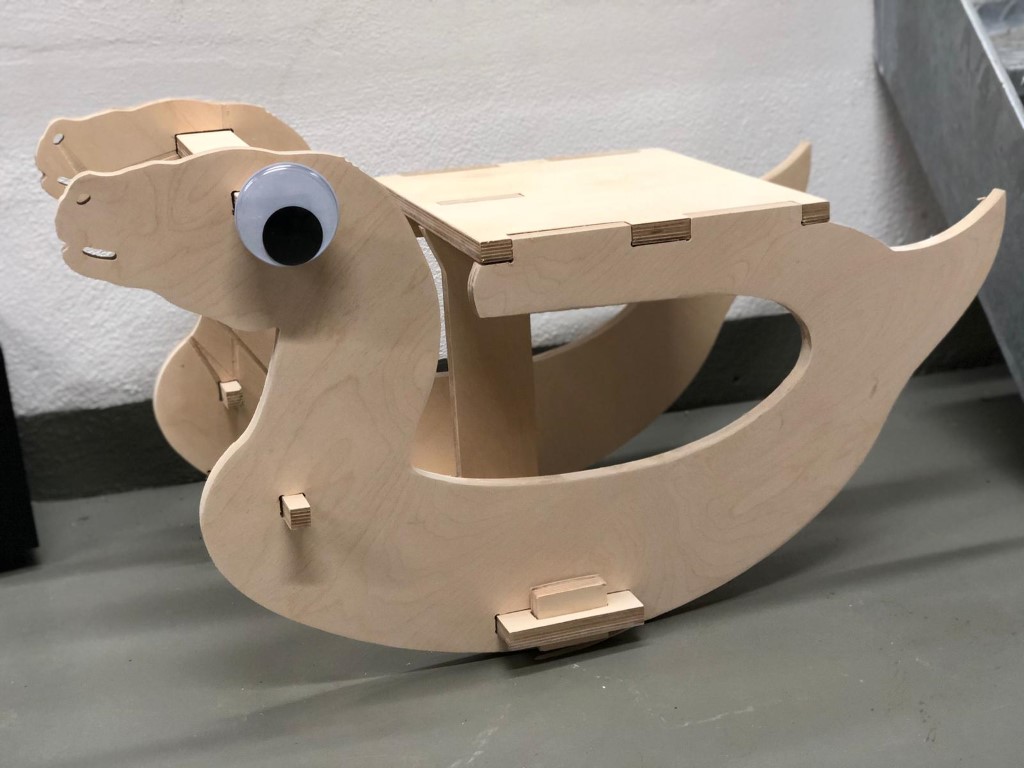
This is the finished result!
And this is how it looks from the inside:
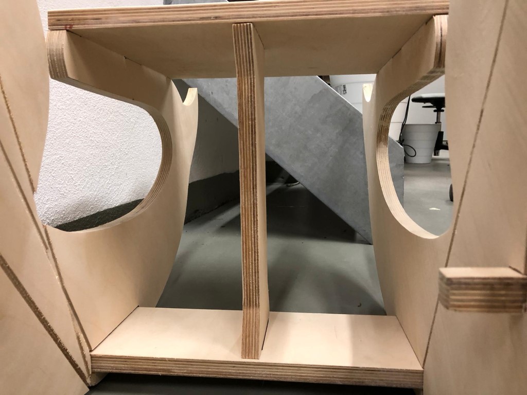
Not pretty but it was hard to keep the wood down once it is detached (the wood wasn't plane even though I screwed it down in the corners. I guess I needed more screws but it was hard to place them since I used the whole cutting area).
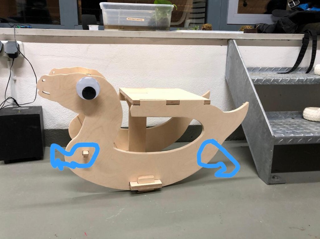
Here I'm testing it out. It worked!

It was very dangerous actually so I decided to improve it in the future with "brakes", like this: