Exercise, Week 11 - Output Devices
Group Assignment - Measure the power consumption of an output device.
This
is a group assignment done with Ting Kok
Eng and Noel
Kristian.
Our collective work is documented on the SP Fablab
Website Assignment 8 and hence only my learning and reflections are
documented here
Individual Assignment - Add an DC motor to a microcontroller board I had designed, and program it to do turns.
Our Fablab is currently closed because of COVID19, and I had to try doing my assignment using available resourses and work at home. For this week, I had controlled a 6 volts DC motor with a L298N driver module (using OUT3 and OUT4 pins from L298N driver module) and a Arduino UNO (using D8, D9 and D10 from Arduino UNO).
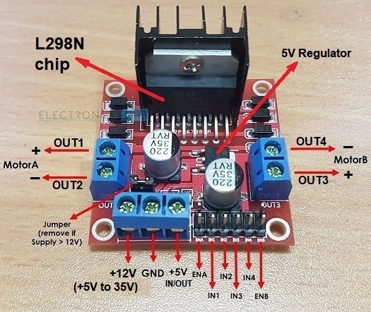
Picture of a L298N driver module (1)
L298N Driver Module
The L298N driver module is an integrated monolithic circuit in a 15-lead Multiwatt based on the L298N heavy-duty dual H-bridge controller. It is a high voltage, high current dual full-bridge driver designed to accept standard TTL logic levels and drive inductive loads such as 2 DC motor (up to 2A each), 2 relays, 2 solenoids or a stepping motor. There are two enable inputs (ENA and ENB) provided to enable or disable the device independently of the input signals (2), this allow user to control the speed of two DC motors. And 2 pair of gates inputs (IN1, IN2 and IN3, IN4) controls the direction of DC motors. It can control 2 DC motors which operates between 5V to 35V and up to 2A using an external power supply, and it is recommended to use the external voltage supply. The module also has an onboard regulator which helps in giving the output of 5V (5).
Pin Connections for L298N Driver Module, DC Motor and Arduino UNO
Connection of L298N driver module as follow;
1. Motor B: This terminal block will give the output for the my 6V DC motor.
2. 12V Jumper: Keep this jumper in place for my 6V supply voltage and the 5V power pin will give the output of 5V. If the supply voltage is greater than 12V, then remove this jumper and give the 5V supply to the 5V power pin so that the L298 Dual H Bridge IC can work properly.
3. Power Pins: Give 6V supply voltage at the 12V pin and ground. If the supply voltage is greater than 12V (max is 35V), then make sure to remove the 12V jumper. 5V pin will act as Output if the Vs will be less than 12V, and 5V pin will act as Input if the Vs will be greater than 12V (max 35V).
4. Enable Pin: Remove the jumpers Enable B and connect this pin to PWM pins of Arduino, this allow me to control the speed of a DC motor. Keeping the jumper on this pin means that I will not able to control the speed of DC motors.
5. Logic Pins: Connect the IN3 and IN4 (Logic pins) to digital pins (D8,D9 and D10) of Arduino UNO. These will help in controlling the rotation and speed of DC motors.
6. 5V linear Regulator: This will step down the supply voltage to 5V and will give the output at the 5V pin.
There are 4 wires connecting from Arduino UNO to the L298 driver module,
1. Arduino UNO D8 is connected to L298 driver module IN3
2. Arduino UNO D9 is connected to L298 driver module IN4.
3. Arduino UNO D10 is connected to L298 driver module ENB.
4. Arduino UNO GND pin is connected to L298 driver module GND pin.
I had used a 6 volts DC adaptor to drive my 6 volts DC motor, to get this working there are 2 wires connecting the DC adaptor to L298 driver module.
1. DC adaptor positive wire is connected to L298 driver module 12V pin.
2. DC adaptor negative wire is connected to L298 driver module GND pin. Note when using 2 seperate power supply for Arduino UNO and L298N driver module, ensure ground is common on both setup.
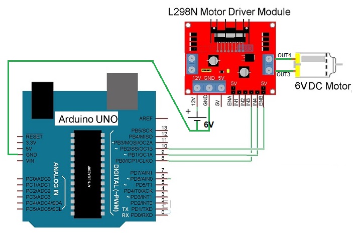
Circuit diagram the connection of a DC motor with L298 and a Arduino UNO (1)
Using Audrino IDE to program Arduino UNO to control a L298N Driver Module connected to a DC motor
This is a program code for Arduino UNO to control a L298N driver module connected to a DC motor. And the DC motor will ...
1. turn clounter cockwise ,
2. turn clockwise,
3. stop turning
4. and changes its revolutions per minute (RPM).

Description of Program Code
1. Initialized motor connections Enable B, IN3, and IN4 as Arduino UNO D5, D7 and D6. Than set all motor control pins as output i.e. pinMode(enB, OUTPUT), pinMode(in3, OUTPUT), pinMode(in4, OUTPUT).
2. In function demoOne(), motor will run in counter clockwise direction by setting IN3 high "digitalWrite(in3, HIGH)" and setting IN4 low "digitalWrite(in4, LOW)". And set speed to 200 out of possible range 0 to 255.
3. Next, motor will run in clockwise direction by setting IN3 low "digitalWrite(in3, LOW)" and setting IN4 high "digitalWrite(in4, HIGH)". And set speed to 200 out of possible range 0 to 255.
4. Then, motor will stop turning, operating in brake condition. Because setting IN3 low "digitalWrite(in3, LOW)" and IN4 low "digitalWrite(in4, LOW)".
5. In function demoTwo(), motor will run across the range of possible speeds. First set motor to run in clockwise direction by setting IN3 high "digitalWrite(in3, HIGH)" and setting IN4 low "digitalWrite(in4, LOW)". Next, accelerate motor from zero to maximum speed by using a counter 'i' for analogWrite(enB, i) in a "for" loop "for (int i = 0; i < 256; i++)".
6. Next, motor will decelerate from maximum speed to zero by using a counter 'i' for analogWrite(enB, i) in a "for" loop "for (int i = 255; i > 0; --i)".
7. Then, motor will stop turning, operating in brake condition. Because setting IN3 low "digitalWrite(in3, LOW)" and IN4 low "digitalWrite(in4, LOW)".
8. Note both function, demoOne() and demoTwo() are executed continuously in a loop function until a user stop the operation.
Video of a Arduino UNO controlling a L298N Driver Module and driving a DC Motor
I had designed and fabricated a ATtiny44 board in Week 9: Input Devices for this week execrise. As I had completed this execrise working at home when our FabLab was closed, so I will not used my ATtiny44 board for this week execrise.
Please refer to Input Devices to understand the design and fabrication process of ATtiny44 board.
Source Codes for Arduino UNO
1. Arduino UNO controlling a L298N driver module and driving a DC Motor, right mouse click and save link: wk11DCmotor.ino
What I have learned:
1. A Pulse Width Modulation (PWM) Signal is a technique for generating digital pulses to control an analog circuit or control DC motors, it consists of a duty cycle and a frequency.
2. L298N driver module can control two DC motor or a single bipolor stepper motor, and it can control direction and speed of DC motors.
3. The voltage drop of the L298N driver module is about 2V, this is due to the internal voltage drop in the switching transistors in the H-Bridge circuit. This means that a 12V DC motor will never spin at its maximum speed when connecting a 12V to the motor power supply terminal because the motors will receive voltage around 10V only (4).
4. When using 2 seperate power supply for Arduino UNO and L298N driver module, ensure ground is common for both.
Citation
1. Reference from URL on 22/04/2020: https://www.electronicshub.org/arduino-dc-motor-control-using-l298n/
2. Reference from URL on 22/04/2020: https://www.sgbotic.com/index.php?dispatch=products.view&product_id=2579
3. Reference from URL on 22/04/2020: https://www.circuitmagic.com/arduino/how-to-control-dc-motor-with-l298n-driver-and-arduino/
4. Reference from URL on 22/04/2020: https://lastminuteengineers.com/l298n-dc-stepper-driver-arduino-tutorial/
5. Reference from URL on 22/04/2020: https://electronicshobbyists.com/controlling-dc-motors-arduino-arduino-l298n-tutorial/