Final Project Process
My final project process incorporate...
1. Design an ATMega328 microcontroller board using Eagle, mill the board using a Stepcraft 420, assemble and test the board.
2. The fabricated ATMega328 microcontroller board interfacing with a Bluetooth module HC05 and a NeoPixel strip. The circuit is power up by a MT3608 DC-DC Boost Converter regulate a 5 volts output from a Lithium ion cell.
3. Using Arduino IDE to program the fabricated ATMega328 microcontroller board interfacing with a Bluetooth module HC05 and NeoPixel strip.
4. Using Fusion 360 to create a 2D design of my pentagon lighting panels and perform laser cutting for these parts. And assemble the light panel and mounting blocks to form a pentagonal dodecahedron.
5. Using Fusion 360 to create 3D designs of mounting block, core support and a box. And perform 3D printing of the designs to support lighting panels and holding the elecrtonic circuit, NeoPixel strip and a battery.
6. Using MIT App Inventor to program and create an Android App for my Android mobile to communicate with the Bluetooth module HC05 in the circuit.
7. Assemble and integrate all the hardwares and electronic components. And finally test the NeoPixel Night Light.
Designing and Fabricating an ATMega328P microcontroller Board
For my project, I need a microcontroller board to control the operation of
NeoPixel LEDs. And I decided to make an ATMega328P microcontroller
board, this is a microcontroller I had used in my assignments.
I had created a schematic and PCB design for my microcontroller board using EAGLE, and I had used a STEPCRAFT 420 to mill my microcontroller board. To understand how I had use EAGLE and STEPCRAFT, please refer
to my previous exercise Electronics Design.
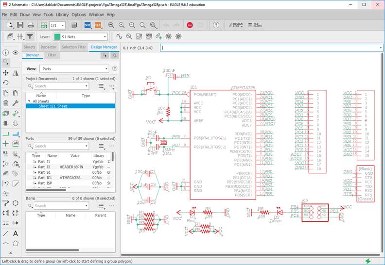
Using EAGLE, I had created an ATMega328P microcontroller schematic.
This is the file, right mouse click and save link: atmega328p.sch
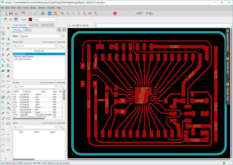
Using EAGLE again, I had created a PCB design for my ATMega328P microcontroller board.
This is the file, right mouse click and save link: atmega328p.brd
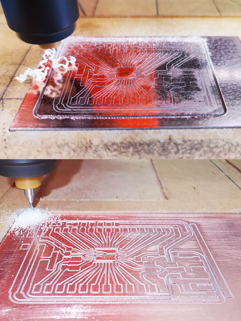
I had generated a gcode file using MODs for STEPCRAFT 420. And using the STEPCRAFT 420 to mill my ATMega328P microcontroller board.
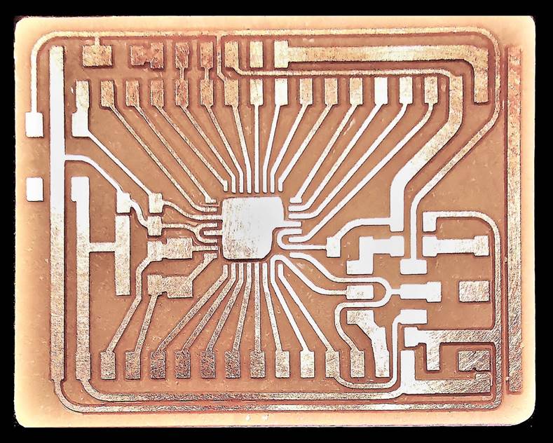
This is my microcontroller PCB milled by a STEPCRAFT 420.
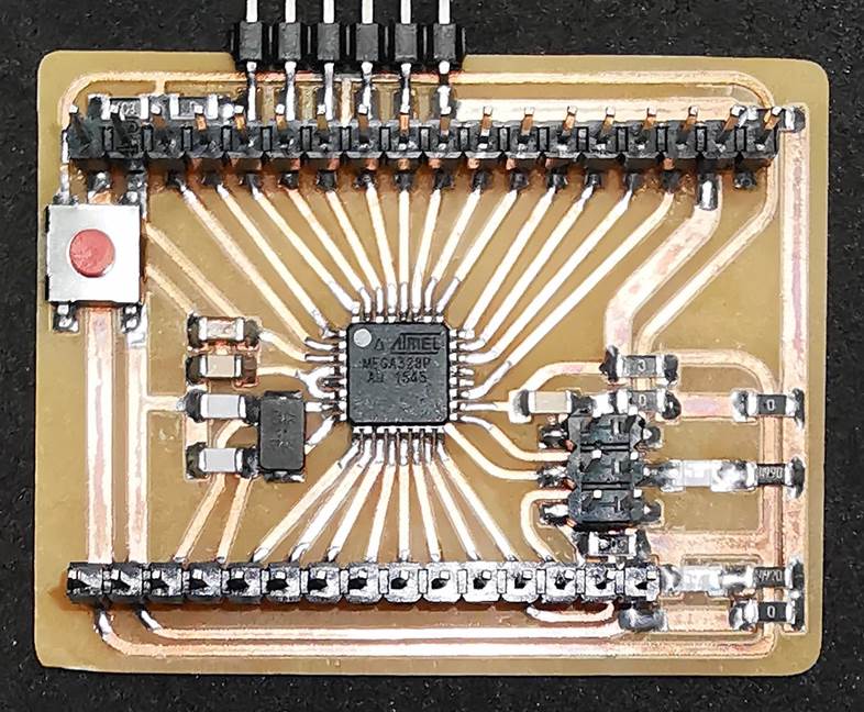
I had assembled my ATMega328P board, next I need to test this board to ensure it is working.
Using Arduino IDE to Program ATMega328P Microcontroller Board
I have decided to use Arduino IDE to program my microcontroller board. To use my microcontroller board, I need to configure a text file in Arduino IDE.
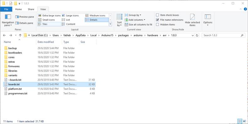
To configure and use Arduino IDE for my fabricated ATMega328P microcontroller board with a 20Mhz crystal, I had edited "boards.txt" and added "Fabkit" definitions into "boards.txt". The path for "boards.txt is "C:\Users\fablab\AppData\Local\Arduino15\packages\arduino\hardware\avr\1.8.3"
This is the file, right mouse click and save link: boards.txt
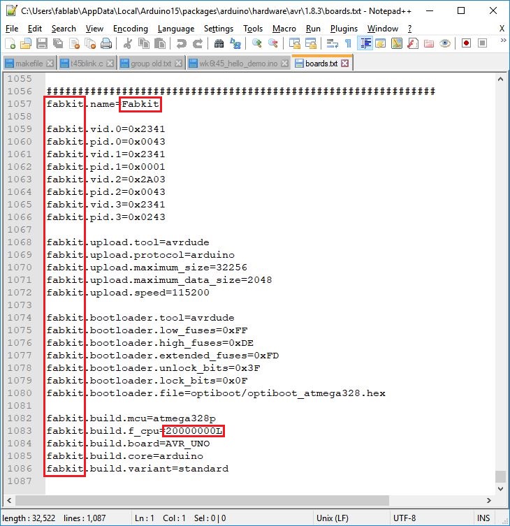
"Fabkit" instructions added into "boards.txt". The instruction "fabkit.build.f_cpu=20000000L" indicated a 20Mhz crystal is used for the ATMega328P microcontroller.
Burning Bootloader and Testing Microcontroller Board
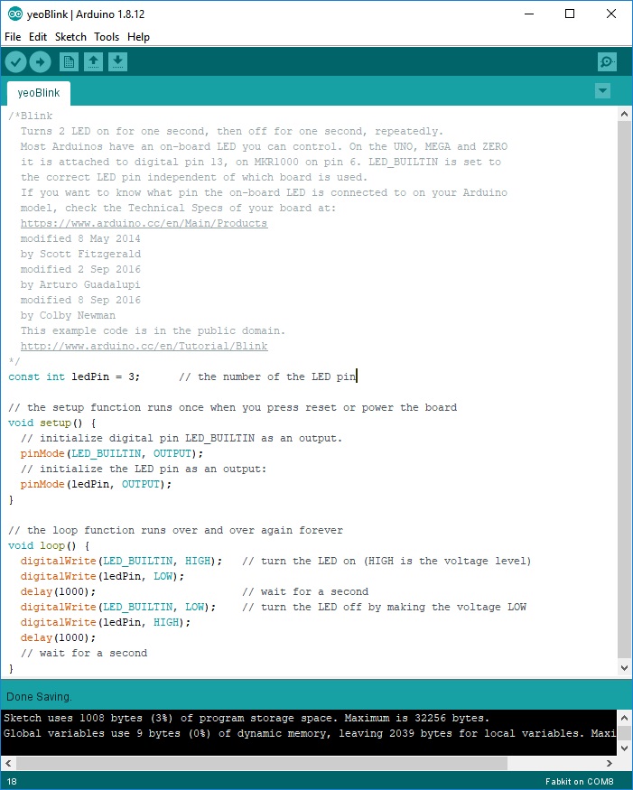
I executed Arduino IDE to burn a Bootloader onto the ATMega328 microcontroller and then I tested my ATMega328P microcontroller board with a program written to blink 2 LEDs.
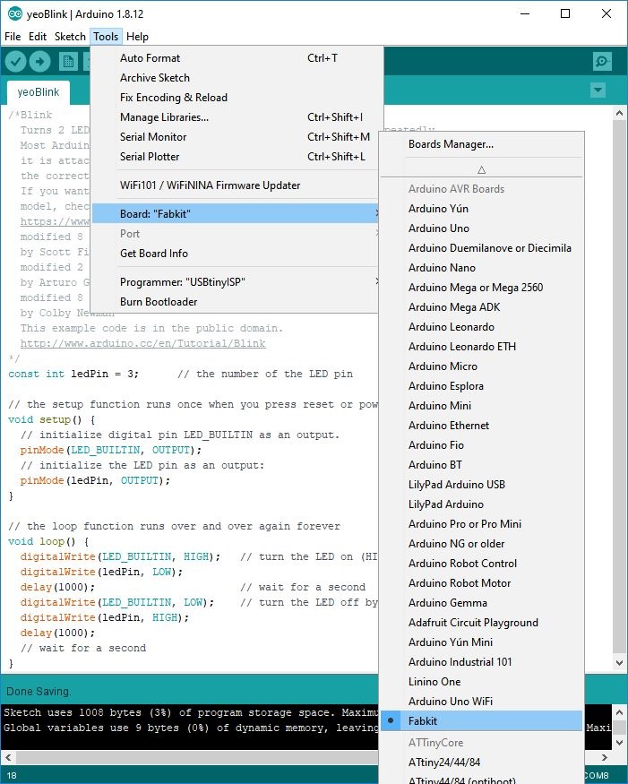
Using board "Fabkit" for my microcontroller board, select Tools>Boards>Fabkit.
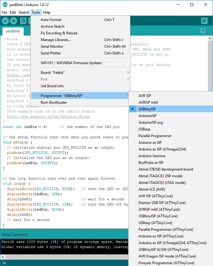
Burn a Bootloader so that I can program my microcontroller board. Connect a programmer "USBtinyISP" to my board, select Tools>Prgrammer>USBtinyISP. Next, select Tools>Burn Bootloader. After burning bootloader, is time for me to program and test my board.
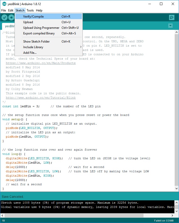
Programming my ATMega328P microcontroller Board with a program to blink 2 LEDs, select Sketch>Verify/Compile. Next, select Sketch>Upload Using Programmer.
This is the file, right mouse click and save link: yeoBlink.ino
I had programmed my ATMega328P microcontroller board to blink 2 LEDs, and successfully made an ATMega328P microcontroller board for my project.
Video for Testing Fabricated Microcontroller Board
Using Fusion 360 to Create Lighting Panels
I had used Fusion 360 to create my lighting panels, and I will laser cut 12 pieces of these panels for my project.
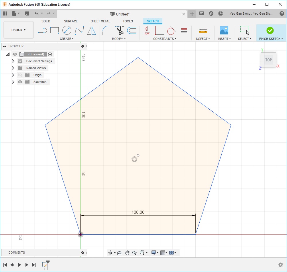
Using Fusion 360, I had created a pentagon lighting panel with 100mm edge length.
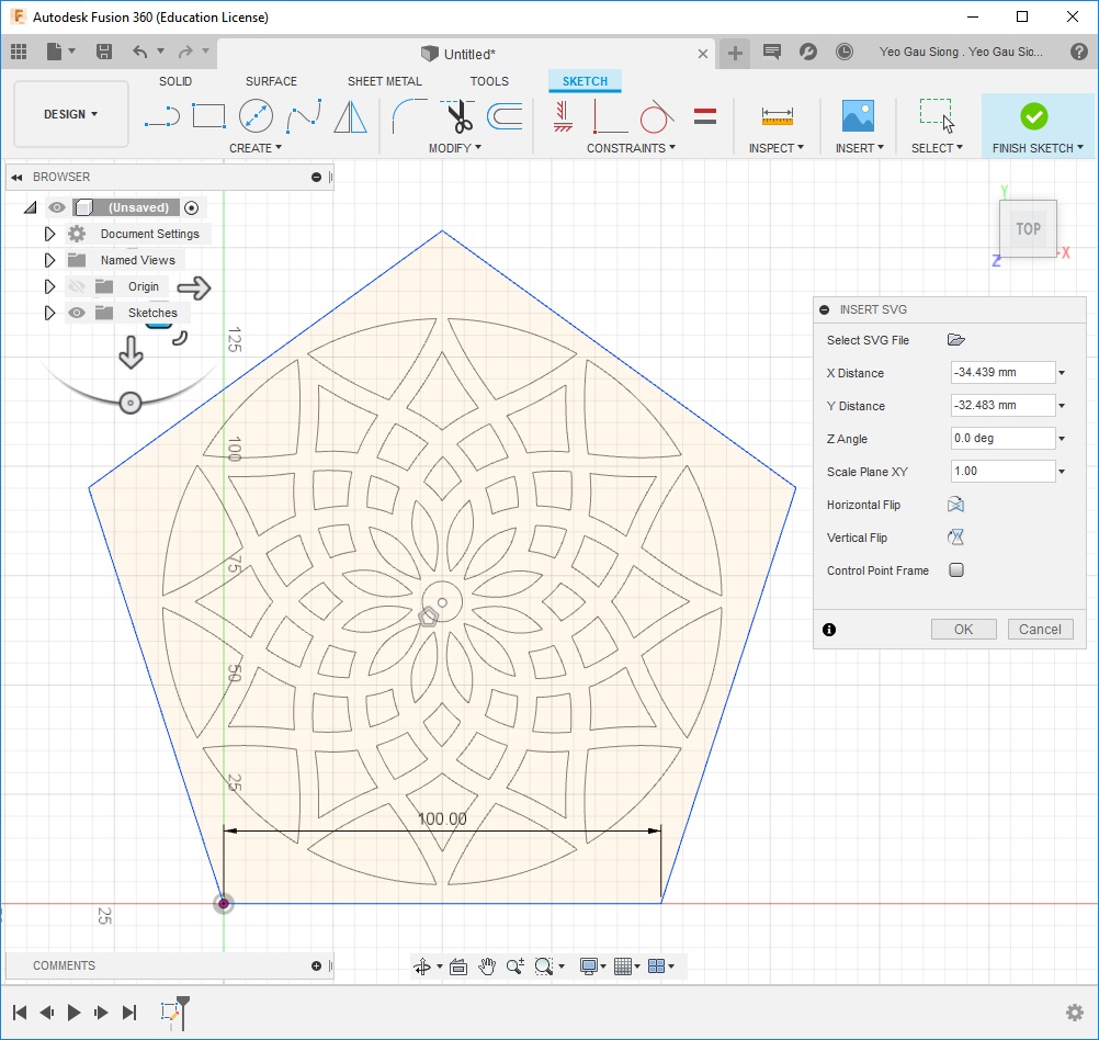
Insert an SVG file into the pentagon to create design for on my pentagon lighting panels(1).
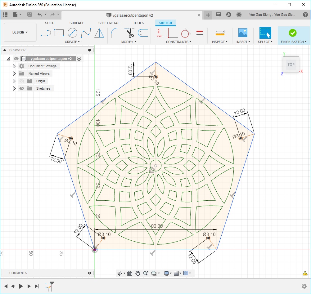
Create 3.1mm holes at the corners of the pentagon, these are mounting holes for the pentagon panels.
This is the file, right mouse click and save link: finalpenals.dxf
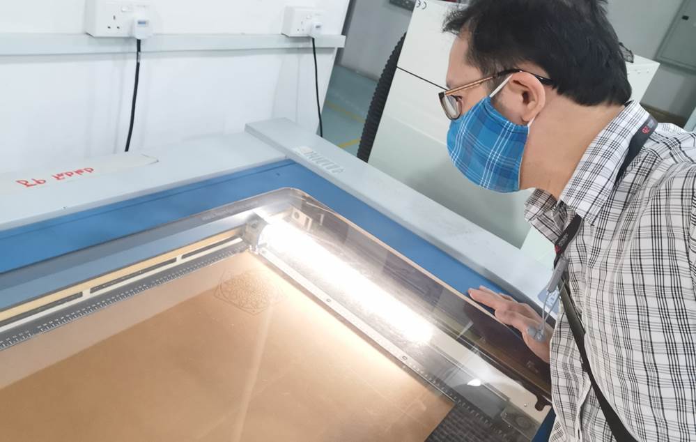
I had used a laser cutter to cut 12 pieces of this pentagon panels on a 3mm thickness translucent acrylic sheet (white).
Using Fusion 360 to Create Mounting Blocks for Lighting Panels
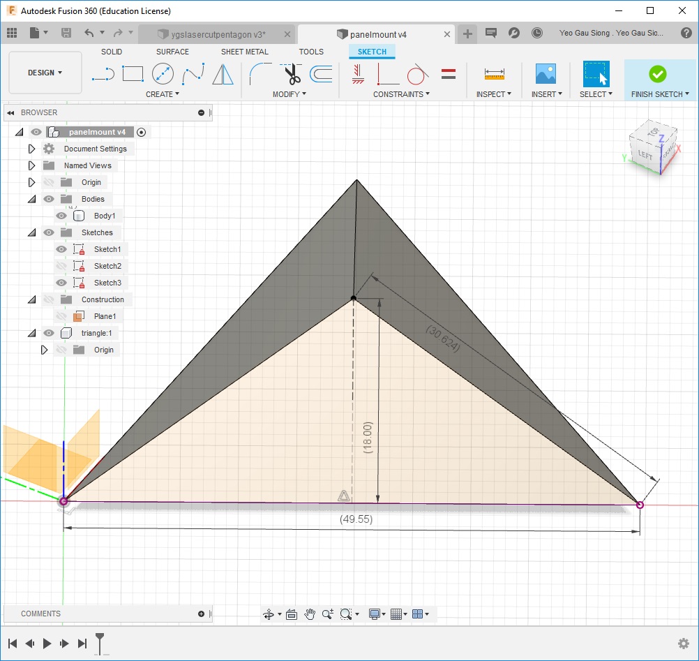
Using Fusion 360, I had created mounting blocks for supporting my lighting panels, and I will 3D print these blocks.
This is the file, right mouse click and save link: panelmount.f3d
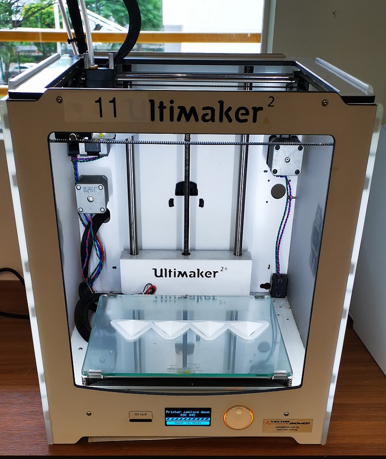
I had used an Ultimaker 3D printer to print 20 pieces of these mounting blocks to support my lighting panels.
Assemble the Casing of NeoPixel Night Light
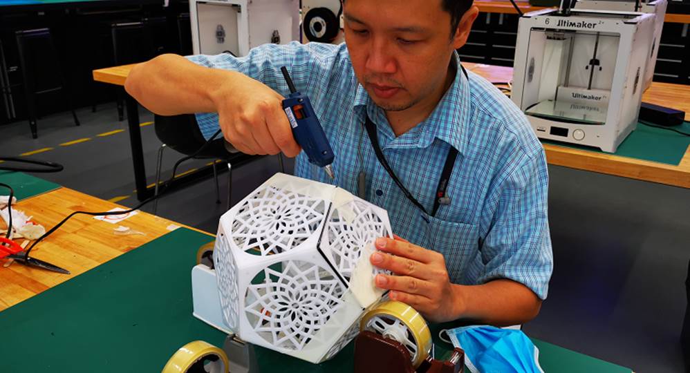
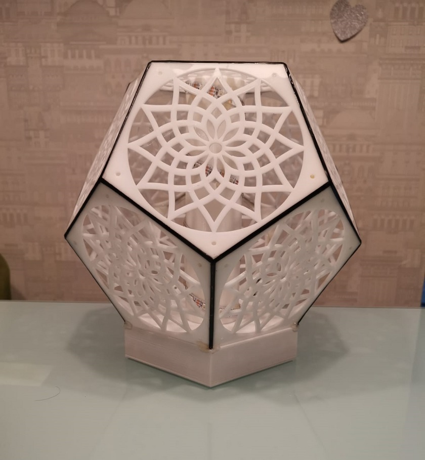
I used hot glue to join all the laser cut pentagon panels together and supported its corners joints from inside with the 3D printed mounting blocks to form a pentagonal dodecahedron.
Using Fusion 360 to Create a Pentagon Box for Electronic Components
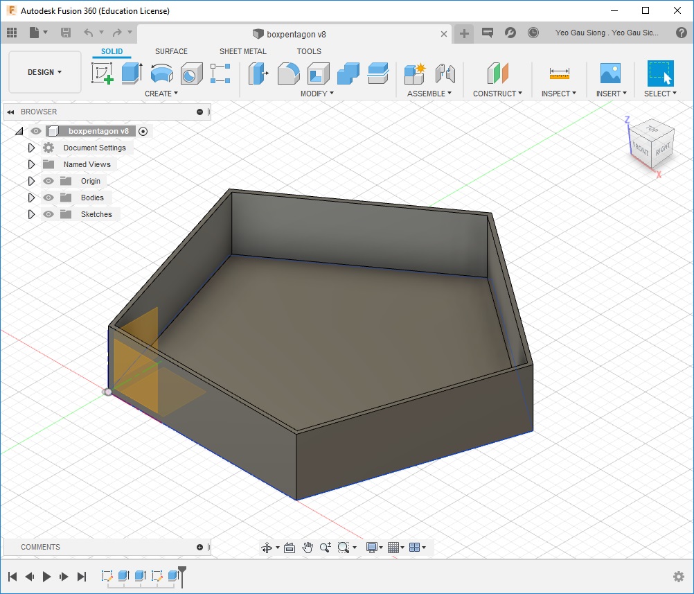
Using Fusion 360, I had created a pentagon box to contain the electronic circuit for my NeoPixel Night Light and I will 3D print this box.
This is the file, right mouse click and save link: boxpentagon.f3d
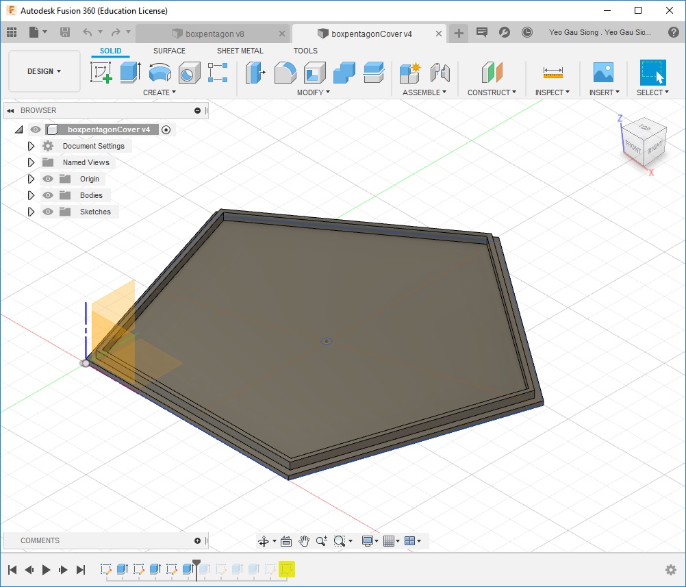
Using Fusion 360, I had created a cover for the pentagon box and I will 3D print this box.
This is the file, right mouse click and save link: boxpentagoncover.f3d
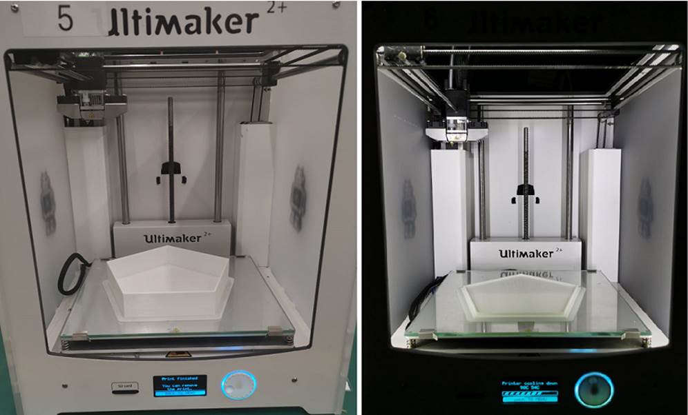
I had used Ultimaker 3D printers to print a pentagon box and a cover for the pentagon box.
Using Fusion 360 to Create the Core for Lighting Panels
I had using Fusion 360 to create the core to support for my NeoPixel. I had divided this core design into 3 separate parts.
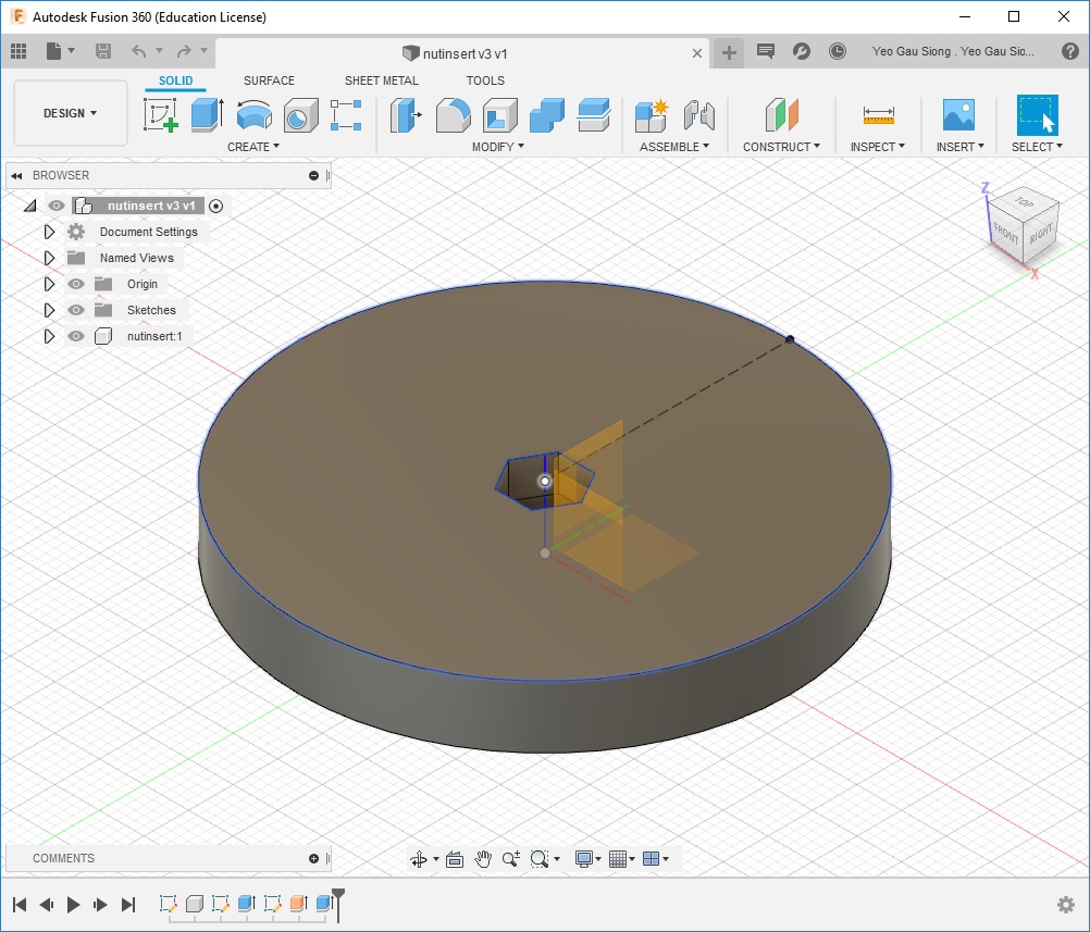
Using Fusion 360, I had created the first core block for inserting nut (4mm nut) and I will 3D print 2 units of these design.
This is the file, right mouse click and save link: nutinsert.f3d
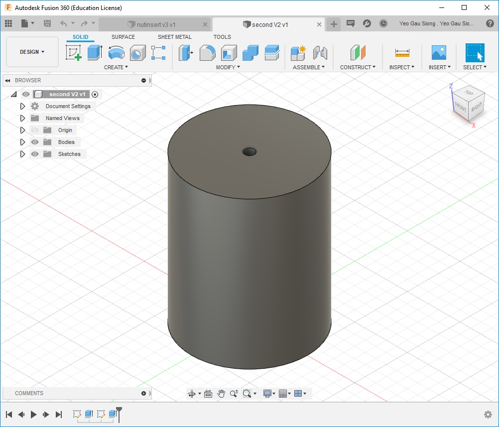
Using Fusion 360, I had created the second piece of the core block and I will 3D print 2 units of these design.
This is the file, right mouse click and save link: secondcore.f3d
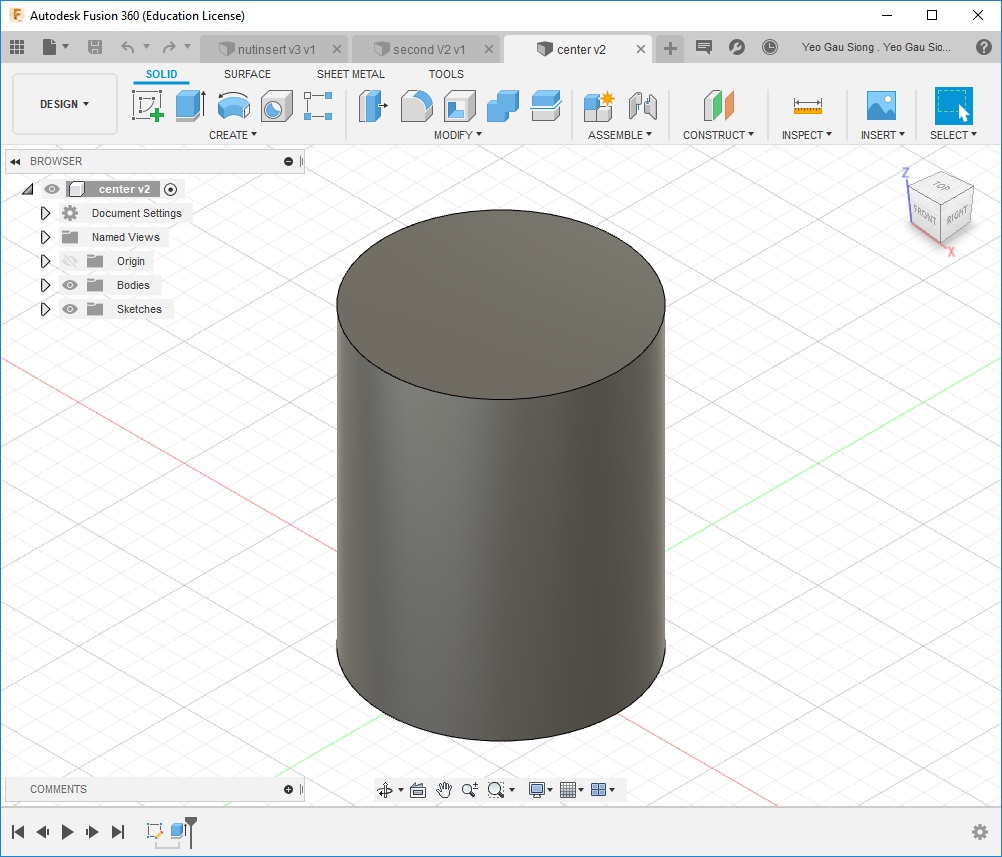
Using Fusion 360, I had created a centre core block and I will 3D print 1 unit of the design.
This is the file, right mouse click and save link: centercore.f3d
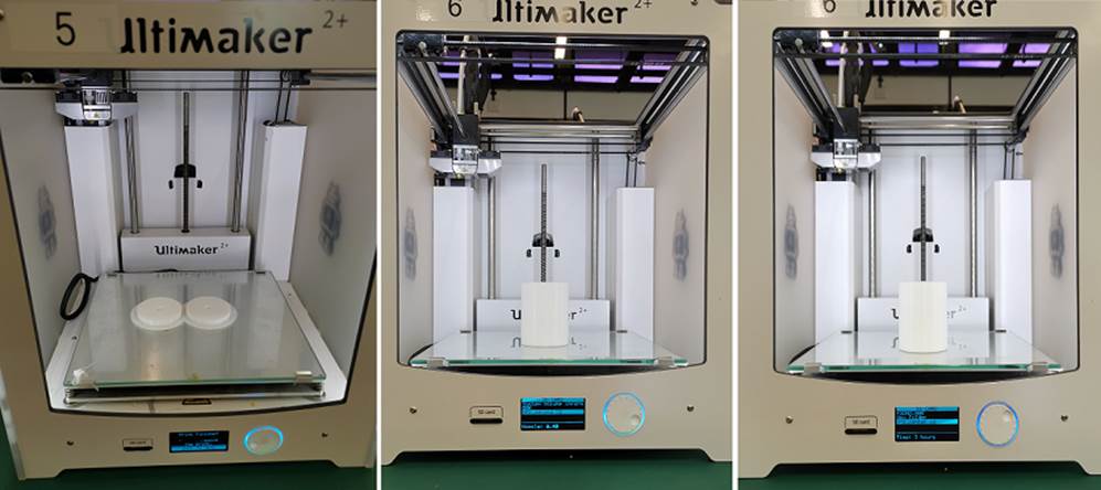
I had used Ultimaker 3D printers to print these cores to support for my NeoPixel. Later I will joint the core parts together.
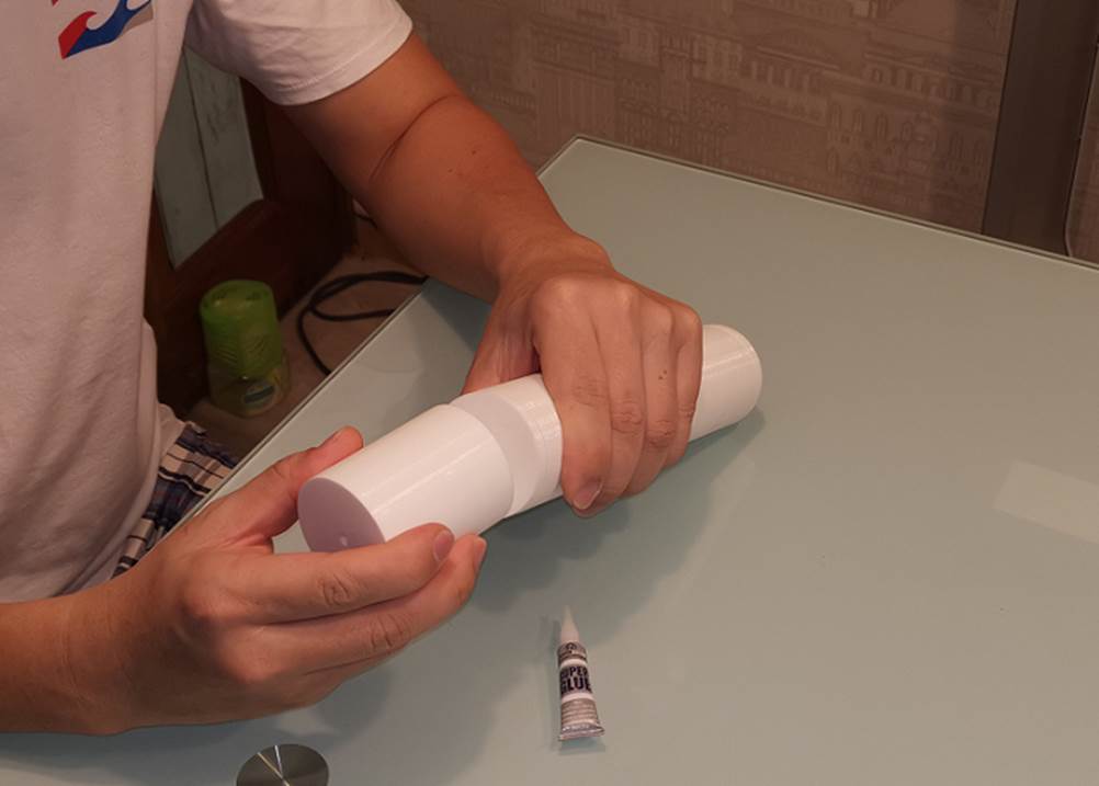
After inserted 4 mm nuts each into the first core blocks, then I joined all the parts together to form a single core unit using super glue.
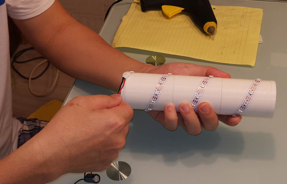
Mounting my NeoPixel strip onto the 3D printed core, there are 39 LEDs on this strip.
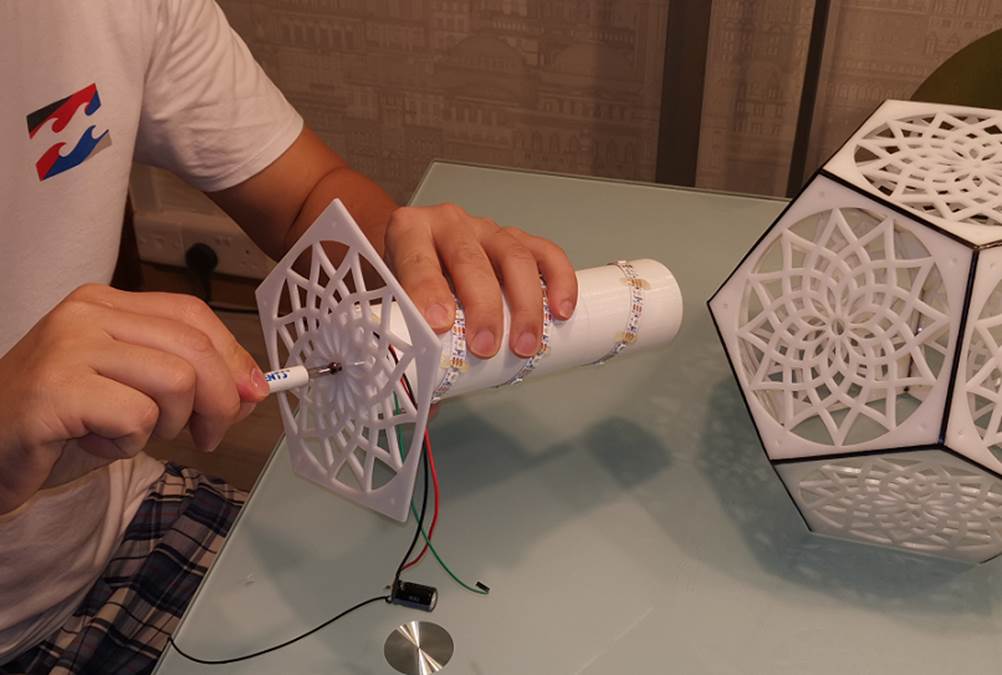
Assemble the cover for the pentagon panels onto the 3D printed core with a 4mm bolt.
After assembling hardware, then I will connect the electronic circuit onto it.
Setting Up and Testing the Electronic Circuit for NeoPixel Night Light
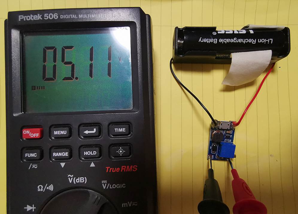
Setting 5 volts output at the MT3608 DC-DC Boost Converter.
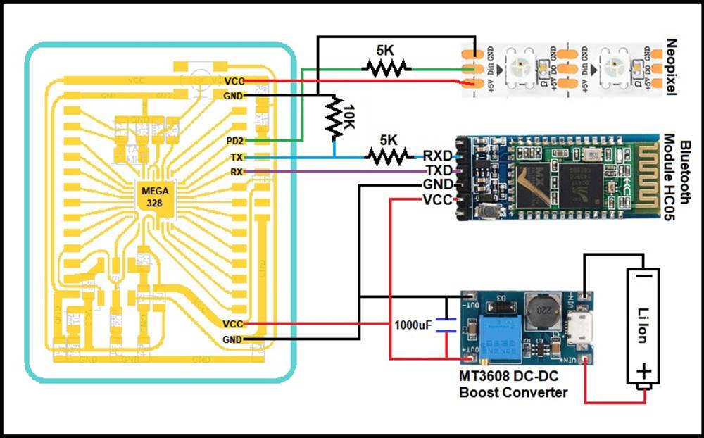
This is the circuit diagram of the NeoPixel Night Light. The parts involve are;
1. A fabricated ATMega328P microcontroller board.
2. A NeoPixel strip with 39 LEDs.
3. A Bluetooth Module HC05
4. A Li ion cell.
5. A MT3608 DC-DC Boost Converter.
6. 2 units of 5K ohm resistor.
7. 1 unit of 10K ohm resistor.
8. 1 units of 1000uF 36V capacitor.
9. And color wires.

After setting up the electronic circuit, I did a testing program on my ATMega328P microcontroller
board and control it with an Android App. And I can control the NeoPixel Strip without problem.
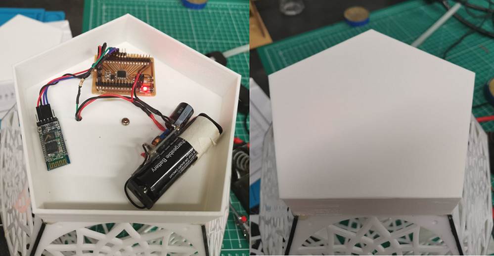
I did a final assemble of the electronic circuit inside the pentagon box and cover it up. And I tested the NeoPixel strip without problem.
I had assembled all the hardware for my NeoPixel Night Light, next is to program my NeoPixel
LEDs.
Arduino Program Code and Android App to Control NeoPixel Night Light
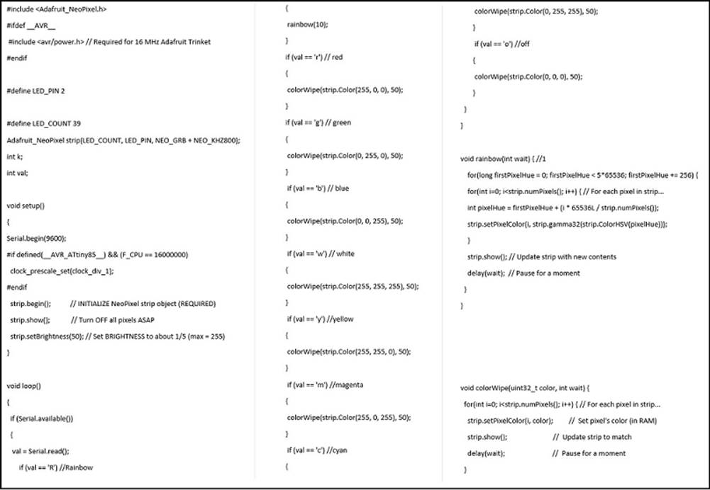
This is the Arduino program code for the LEDs Night Light (2).
This is the file, right mouse click and save link: lednightlight.ino
Description of Arduino Program Code
1. Pin 2 (PD2) is connected to the Din on the NeoPixel strip, this pin control the individually-addressable RGB color pixel.
2. LED_Count are 39 RGB color pixel used in Adafruit_NeoPixel Strip() function.
3. Setup() function with serial communication "Serial.begin(9600)" for Bluetooth module HC05 to receive a character command to change color in colorWipe() function.
4. NeoPixel strip are initialize first "strip.begin()", then turn off "strip.show()" in setup() function. The NeoPixel Strip are then set to 20% brightness "strip.setBrightness(50)" (i.e. max current is 460mA).
5. Loop() function, set 'R' character for rainbow() function, a counter set different color to each pixel.
6. Set 'r' to display red color in colorWipe() function, red with RGB value.
7. Set 'g' to display green color RGB value in colorWipe() function.
8. Set 'b' to display blue color RGB value in colorWipe() function.
9. Set 'w' to display white color RGB value in colorWipe() function.
10. Set 'y' to display yellow color RGB value in colorWipe() function.
11. Set 'm' to display magenta color RGB value in colorWipe() function.
12. Set 'c' to display cyan color RGB value in colorWipe() function.
13. Set 'o' to switch off all display RGB value in colorWipe() function, all zero RGB value.
Using MIT App Inventor, I had created an Android application with Bluetooth controlling
NeoPixel strip (2). (MIT App Inventor: https://appinventor.mit.edu/)
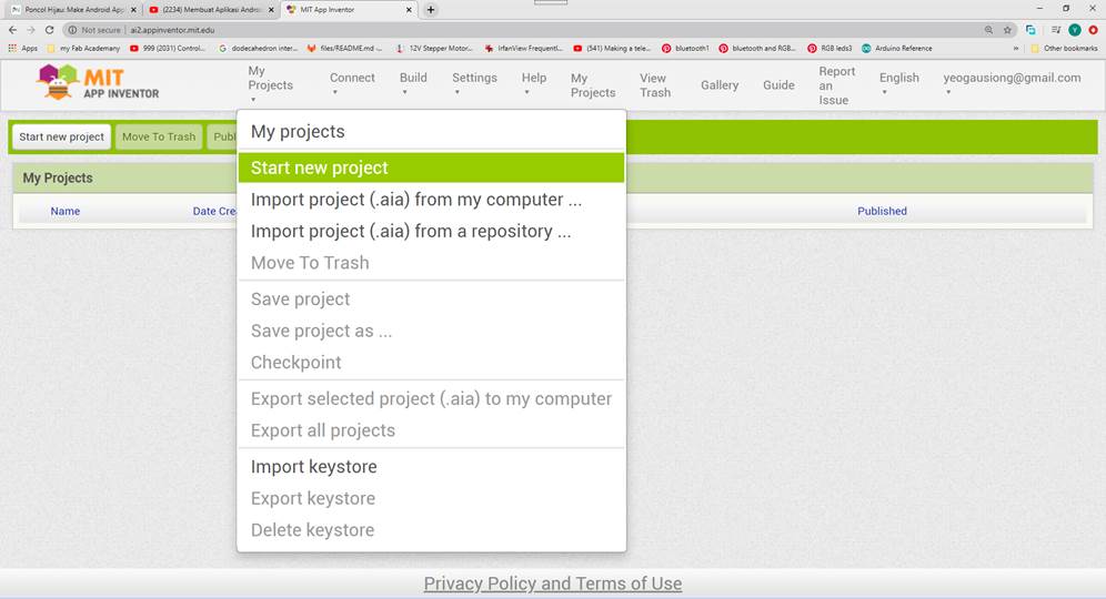
Start a new project, select My Project > Start new project
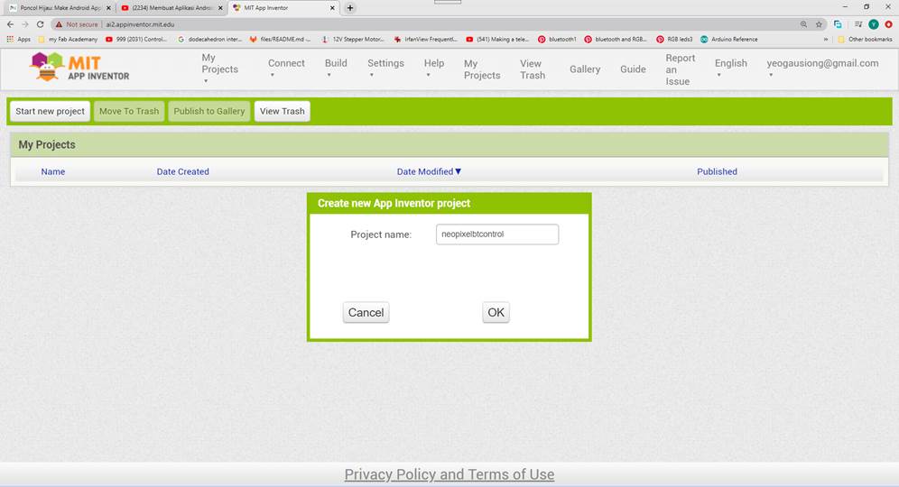
Created a Project name "neopixelbtcontrol"
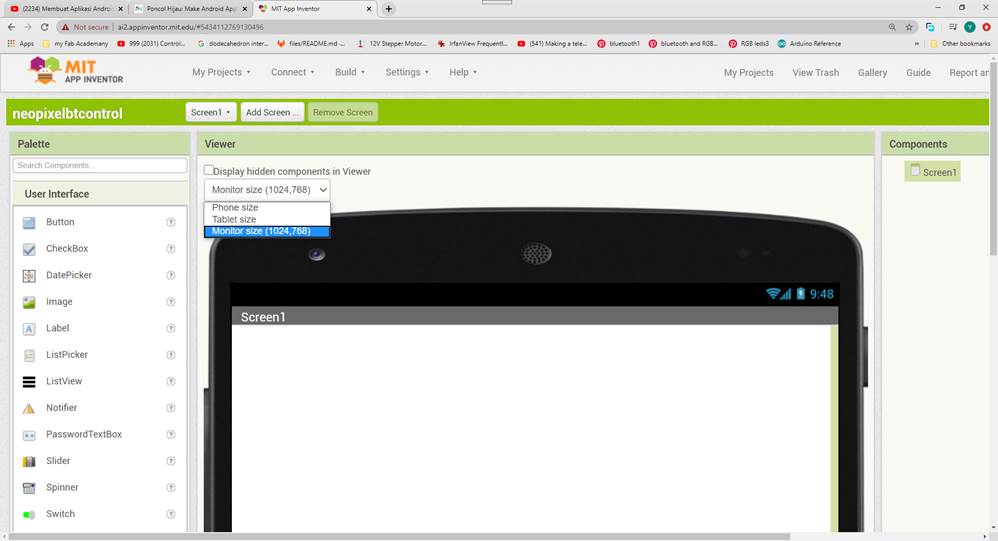
Select Monitor Size because most phones have wide screen.
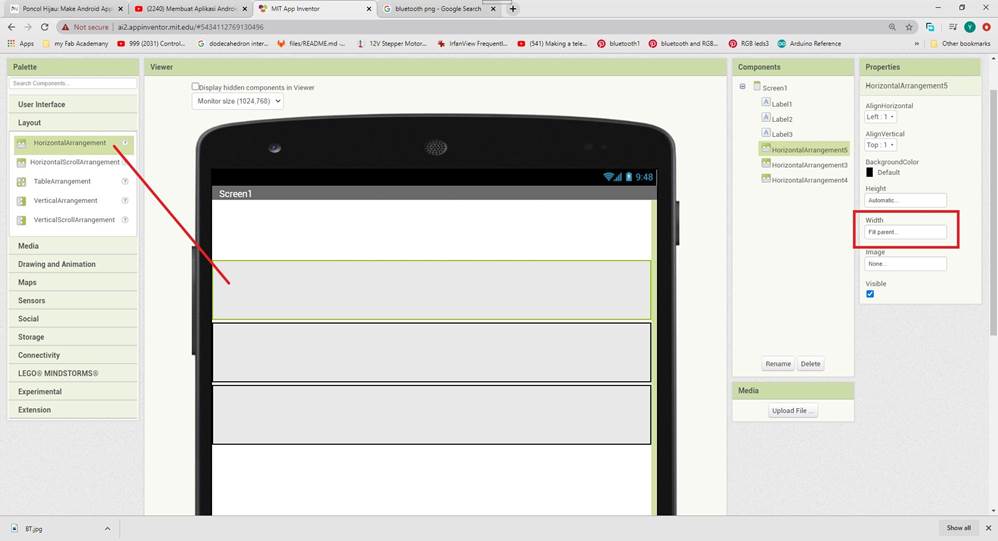
In Layout, select HorizontalArrangement and drag onto the display. Select Width>Fill parent.
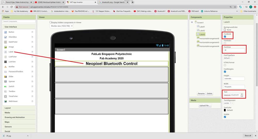
In User Interface, select Label and drag onto the display. Change the text to "NeoPixel Bluetooth
Control" and align the text to centre.
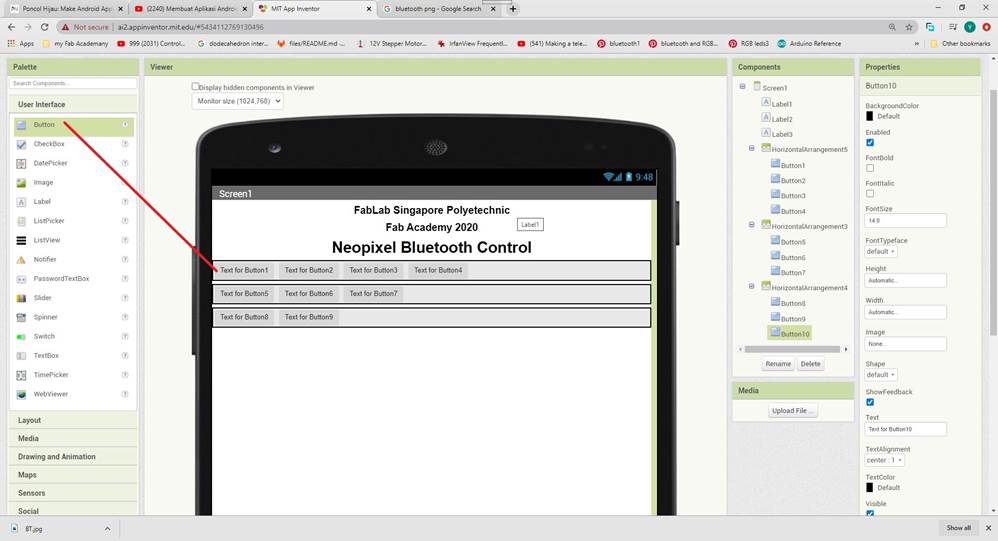
In User Interface, select Button and drag onto the display.
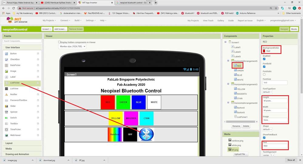
In User Interface, select ListPicker and drag onto the display. Change all the background color and text for the Buttons. Change the images for the Rainbow button and BLUETOOTH ListPicker. In Components window, rename the buttons to match their color.
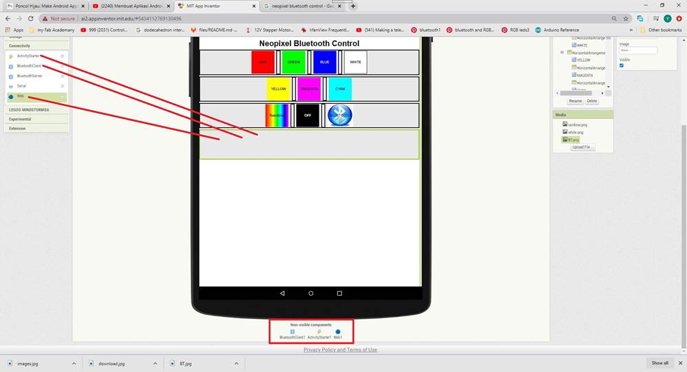
Adding connectivity into a new HorizontalArragnement.
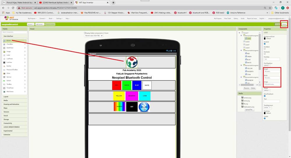
Adding Fab Academy icon. After creating the designer view, I will create the Blocks code for this application. Select Blocks from the top right of the window.
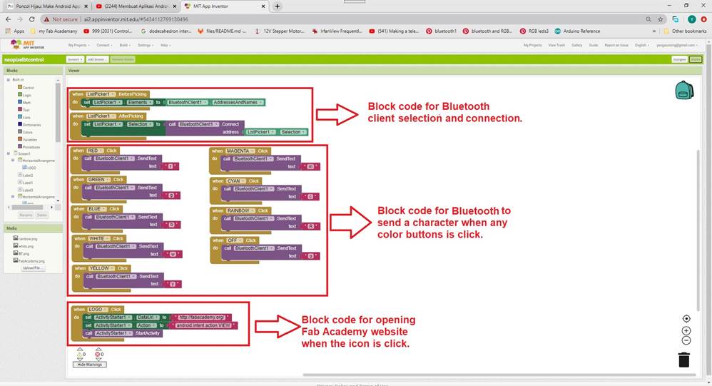
The Blocks codes are divided into 3 main parts.
1. Block code for Bluetooth client selection and connection.
2. Block code for Bluetooth to send a character when any color button is click.
3. Block code for opening Fab Academy website when the icon is click.
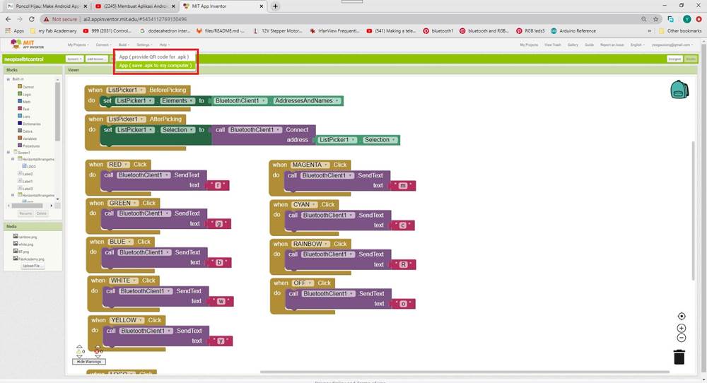
I had created my Android application using MIT App Inventor. Save this application to my computer, select Build>App (save .apk to my computer).
This is the file, right mouse click and save link: neopixelbtcontrol.apk
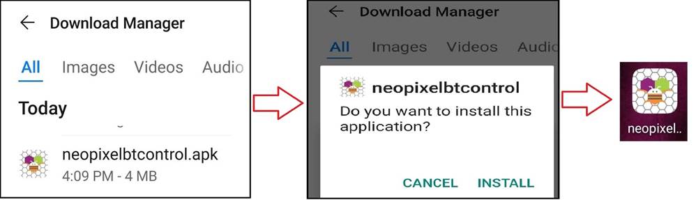
After saving application, transfer "neopixelbtcontrol.apk" to my Android mobile phone and install it. After installation, an icon "neopixelbtcontrol" will appear on my mobile phone.
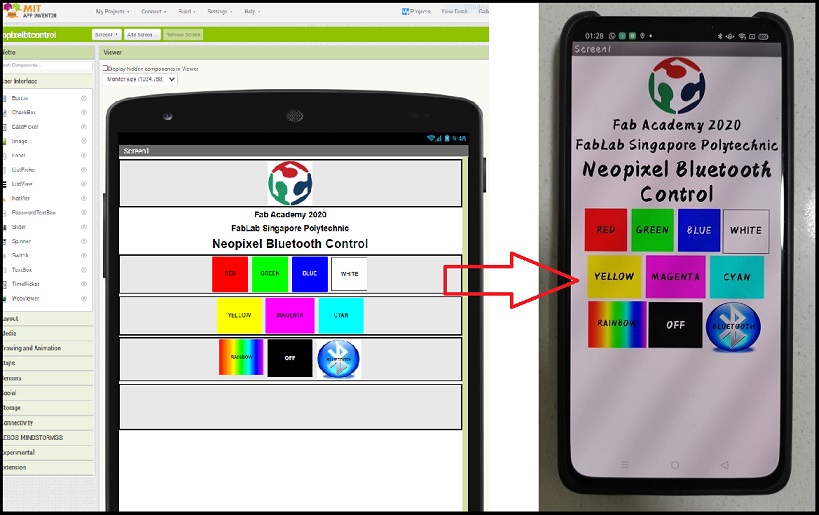
After executing this Android app "neopixelbtcontrol", my mobile screen will display the application created in MIT App Inventor. This Android appcontains different 7 colors button and a rainbow color button to control NeoPixel to display different colors, there is a switch off button for NeoPixel and a Bluetooth connection button that require user to make a connection. And finally, clicking the FabLab icon on the top will launch FabLab website.
Video Testing the NeoPixel Night Light
Please refer to Final Project Result for the summary of NeoPixel Night Light.
Citation
1. Reference from URL on 20/07/2020: https://www.freepatternsarea.com/designs/circle-trivets-hot-pad-coaster-scroll-saw-patterns/
2. Reference from URL on 20/07/2020: http://www.poncolhijau.web.id/2020/05/kontrol-led-rgb-ws2812b-dengan-android.html
3. Reference from URL on 20/07/2020: http://www.poncolhijau.web.id/2020/05/membuat-aplikasi-android-dengan-mit-app.html