12. Input devices⚓︎
-
- Probe an input device(s)’s analog and digital signals.
- Document your work (in a group or individually).
-
Individual assignment
- Measure something: add a sensor to a microcontroller board that you have designed and read it.
-
Learning outcomes
- Demonstrate workflows used in sensing something with input device(s) and MCU board.
-
Have you?
- Linked to the group assignment page.
- Documented what you learned from interfacing an input device(s) to microcontroller and how the physical property relates to the measured results.
- Documented your design and fabrication process or linked to previous examples.
- Explained the programming process/es you used.
- Explained problems and how you fixed them.
- Included original design files and source code.
- Included a ‘hero shot/video’ of your board.
This is a key moment to start relating the week’s work to the final project, although this is something that should have been done since the first weeks of FabAcademy. That’s why our instructors Nuria, Pablo and Adrian have suggested that we try to relate as much as possible the sensor(s) we are going to test this week to our final project.
Therefore, and although my final project is not completely defined, my first intention for this week was to test a water level sensor. Other students from previous years had managed to make some homemade prototypes. This model by Carolina Soto is a simple and apparently effective version, but somewhat obsolete, and since there are currently quite simple water level sensors for Arduino I thought it would be easy to make one with my own design.
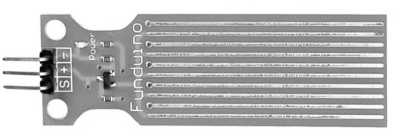
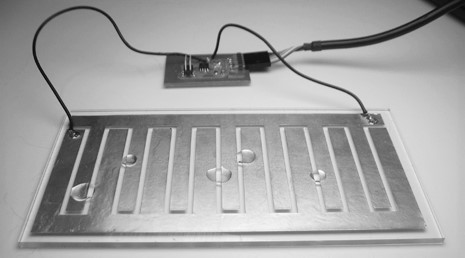
The problem is there isn’t any schematic available for that type of sensor or there are too complex like this one. I tried making one from all the product photos that I could find in the internet but they are made off a two layer board and use a NPN Transistor (usually the J3Y S8050 NPN 40V 1,5A) which we don’t have at the lab or the compatible ones.
Finally searching for other water level sensor types and how they work I found this video that revealed me that water level can be measured with an ultrasonic sensor, and since in fablab it is a sensor that they use a lot for other projects, I thought it would be easy to have access to it.
Hello.t412.input.sergio⚓︎
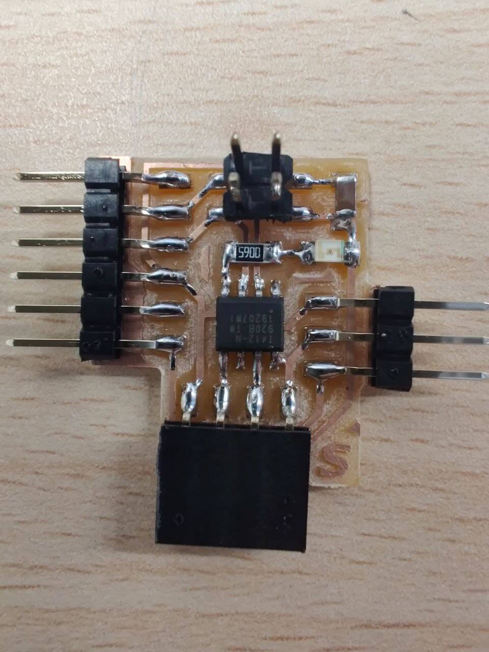
As I am going to use an ultrasonic sensor in the end but I might want to try other sensors in the future, or finally build the water level sensor, I have decided to make a generic board that will allow me to connect any other sensor later on, leaving a 4-pin connector for it (VCC, PIN1, PIN2, GND), inspired by Adrian‘s concept with the Adrianino.
I have started using Neil’s hello.t412.echo board as a base point, and upgrading the UPDI connector to the 3-pin connector. We only need to include our sensor on the board, or in this case set the connection pins and put the connector to be able to test multiple sensors.
Design⚓︎
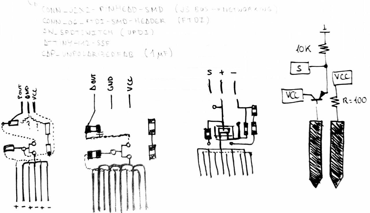
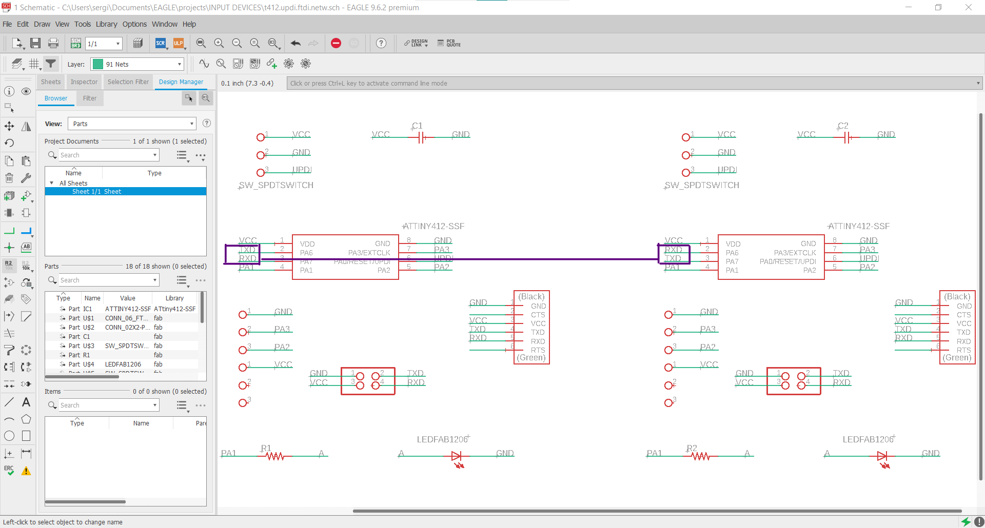
In this case I had to turn again to Adrian to clarify some doubts I had about how to trace all the connectors, finally clarifying that the UPDI would be to program the board (with the FTDI adaptor, hence my doubt) and the FTDI to read the sensor data. He also recommended me to include the 4-pin bus connector for networking in this design, because it will be very useful for that future assignment. So here is the schematic I made in Eagle and all the components used from Fab library and the 412.
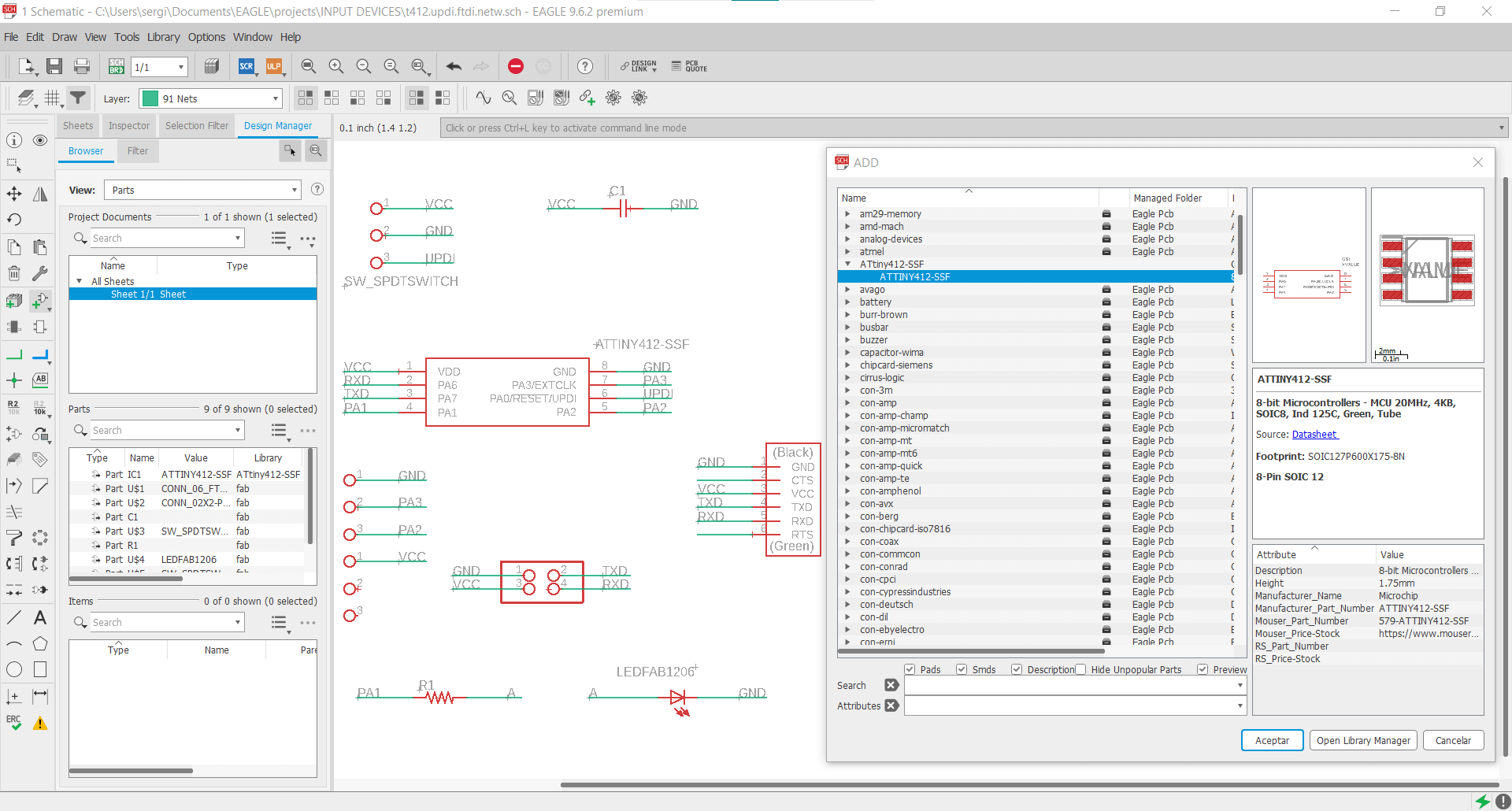
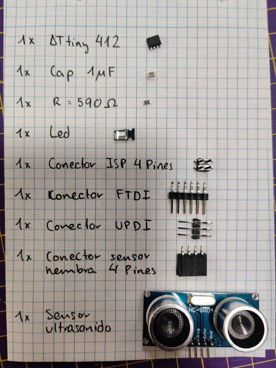
| Component | Librarie name | Quantity |
|---|---|---|
| Microcontroller | ATTINY412-SSF | 1 |
| UPDI connector | SW_SPDTSWITCH | 1 |
| FTDI connector | CONN_06_FTDI-SMD-HEADER | 2 |
| Networking connector | CONN_02x2-PINHEAD-SMD | 1 |
| Capacitor | CAP_UNPOLARIZEDFAB | 1 |
| Resistance | R1206FAB | 1 |
| Led | LEDFAB1206 | 1 |
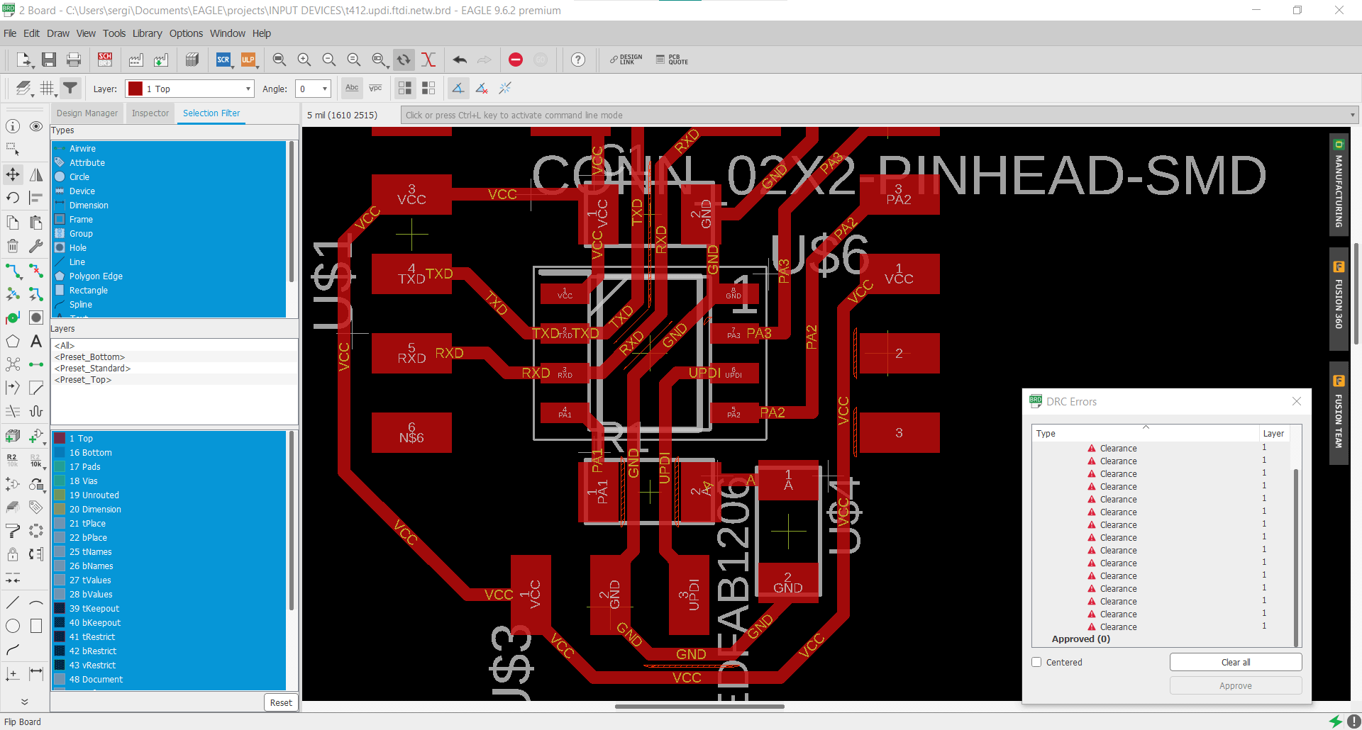
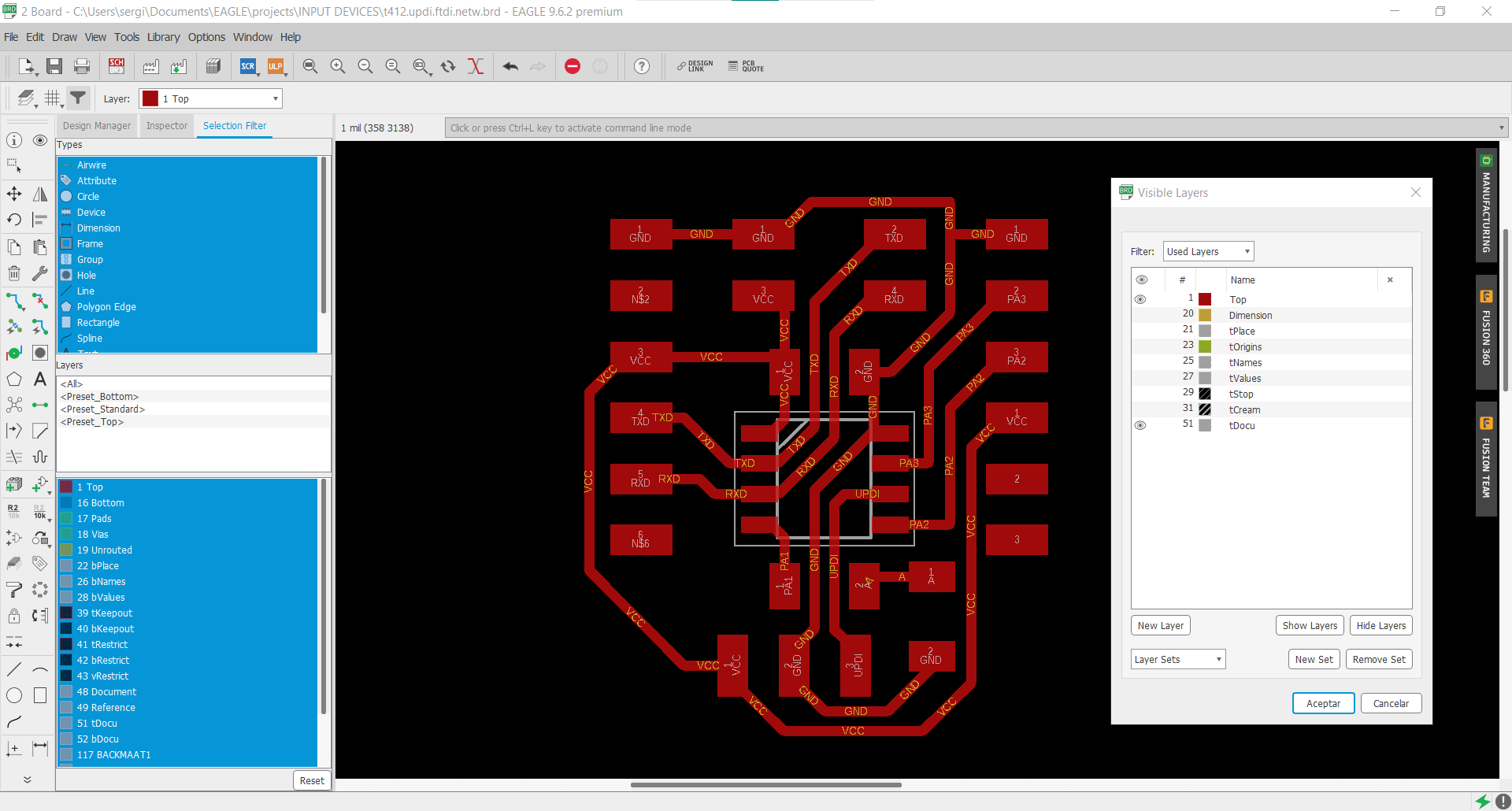
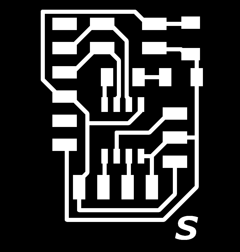
Once the schematic was finished I tried to root all the traces, which was a bit tricky due to all the different connectors, so I had a lot of tight fits between traces and had to adjust a couple of times to leave enough clearence between them. Then we hide all the unnecesary layers and export the image as monochrome, 1000 dpi resolution as explained in the Electronic Design week.
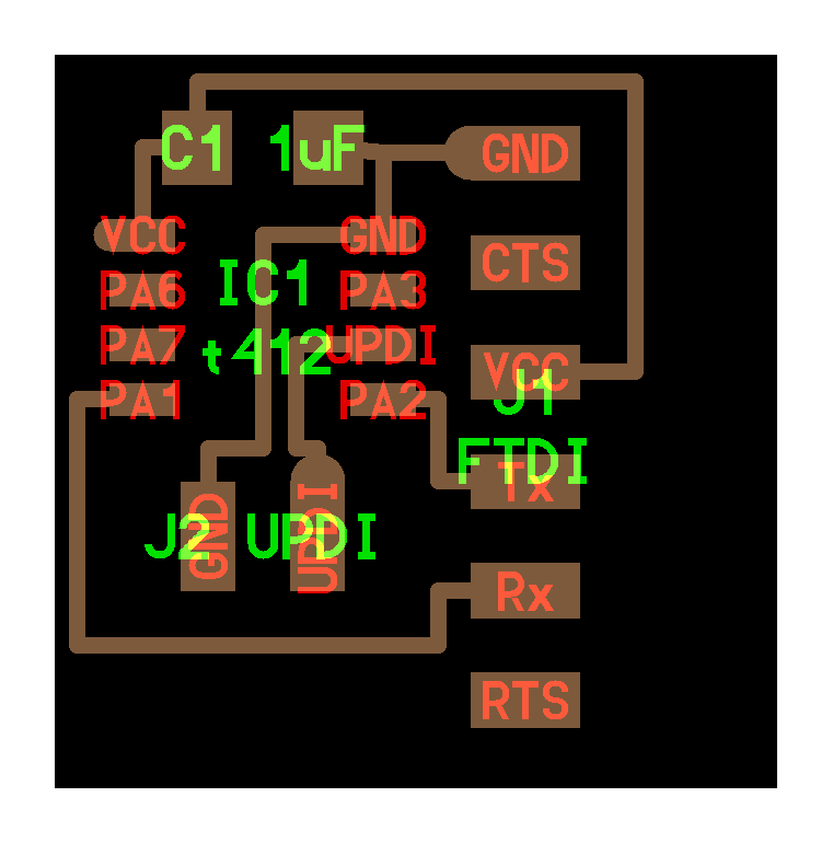
Later, when I had everything ready to mill, Adrian wrote me to warn me two crucial things. First was about using the pins PA6 and PA7 for TXD and RXD and not PA1 and PA2 as Neil was using because, although both pairs work as you can see on this picture of the datasheet, the ones that Neil uses have to be activated by software, having to perform an extra step that is not necessary in this other way (that’s why they are indicated with a small 1 at the top in the form of an asterisk). The second thing and more important, he warned me about pin swapping. As you can see (I didn’t) on Neils board pictured below, he links PA1, which is labeled as TXD in the datasheet as RX on the FTDI conector, and PA2 which is RXD to TX. So I had to redo my board.
At first I focused on just making that changes but as it was designed a bit thight and in that specific way, mixing that would make a mess on the other traces, so I made a copy of the schematic also to remind me for the next time the worng and the right solution.
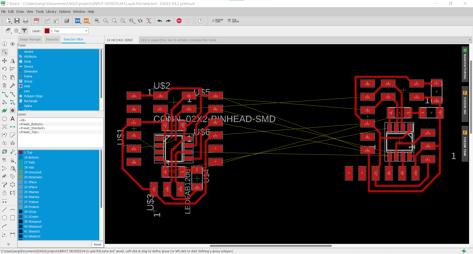
As trying to change the first design would make a mess, I have decided to make one from scratch. Every time I have to re think a board design it comes up much cleaner, so I guess it’s not that bad. Below is a comparison design shot between the old (left) and the new one (right).
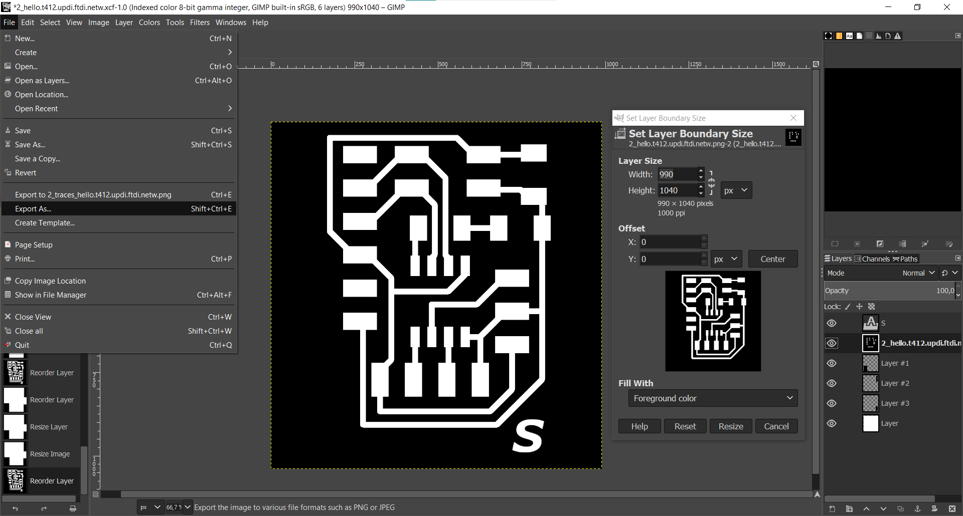
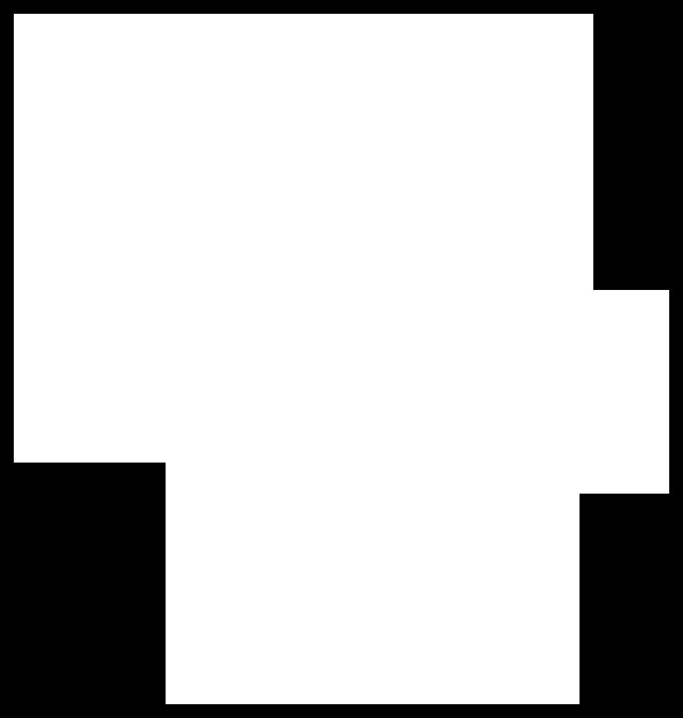
Besides using GIMP to cut the board to size and make the outline, I have decided to leave some parts of the board with more extension to support all the connectors and avoid forcing the solder joints as the only support point. Thats where the Layers #1, #2, and #3 are for.
Fabrication⚓︎
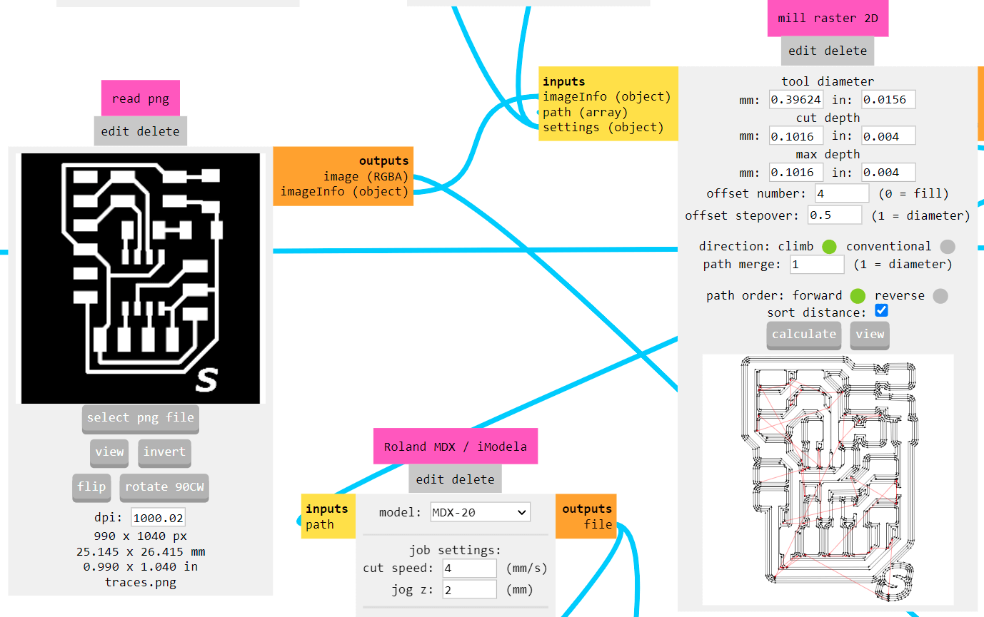
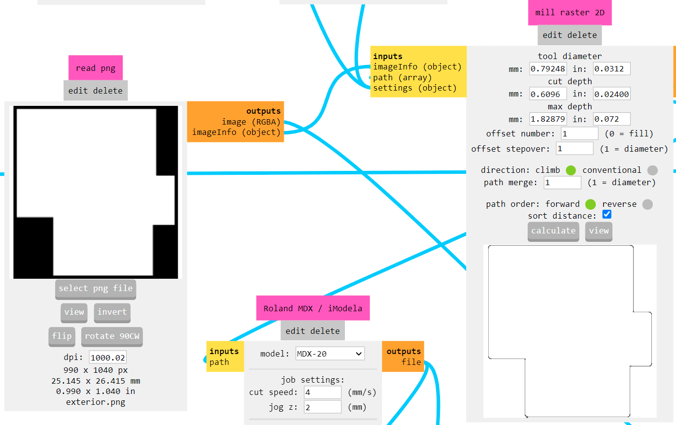
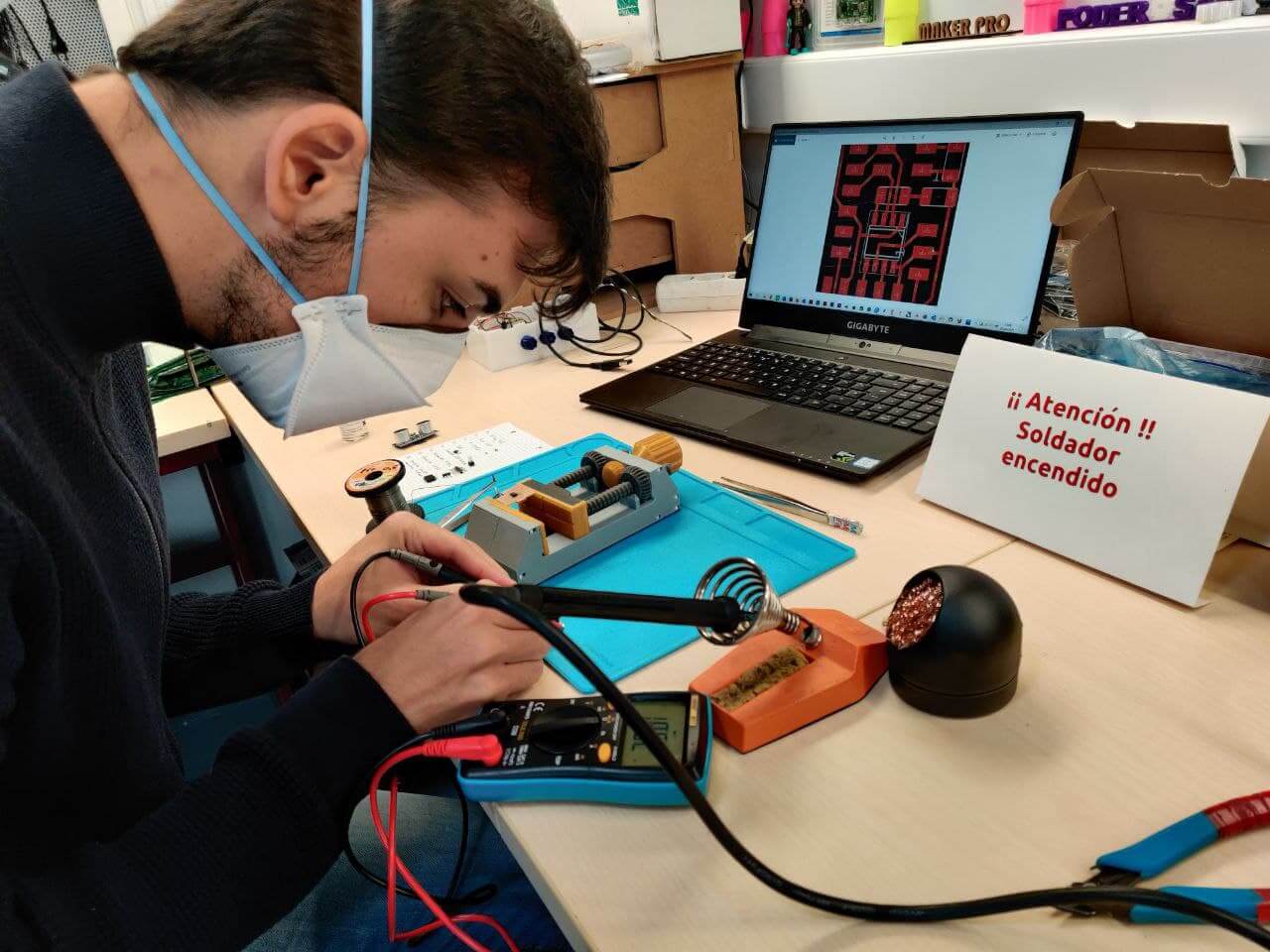
Once the design is finished, it’s time to mill. As in other weeks electronic design process, I used ModsCE to make a final check of the design. This helps me prevent not having any contact or errors between traces when jumping from the png to the milling path, so I can go straight to milling next day at the Lab.
Milling at FabLab Leon is made with the Modela MX-20 and an old Mac with FabModules, as I have explained in other assignments. Below are screenshots of part of that process.
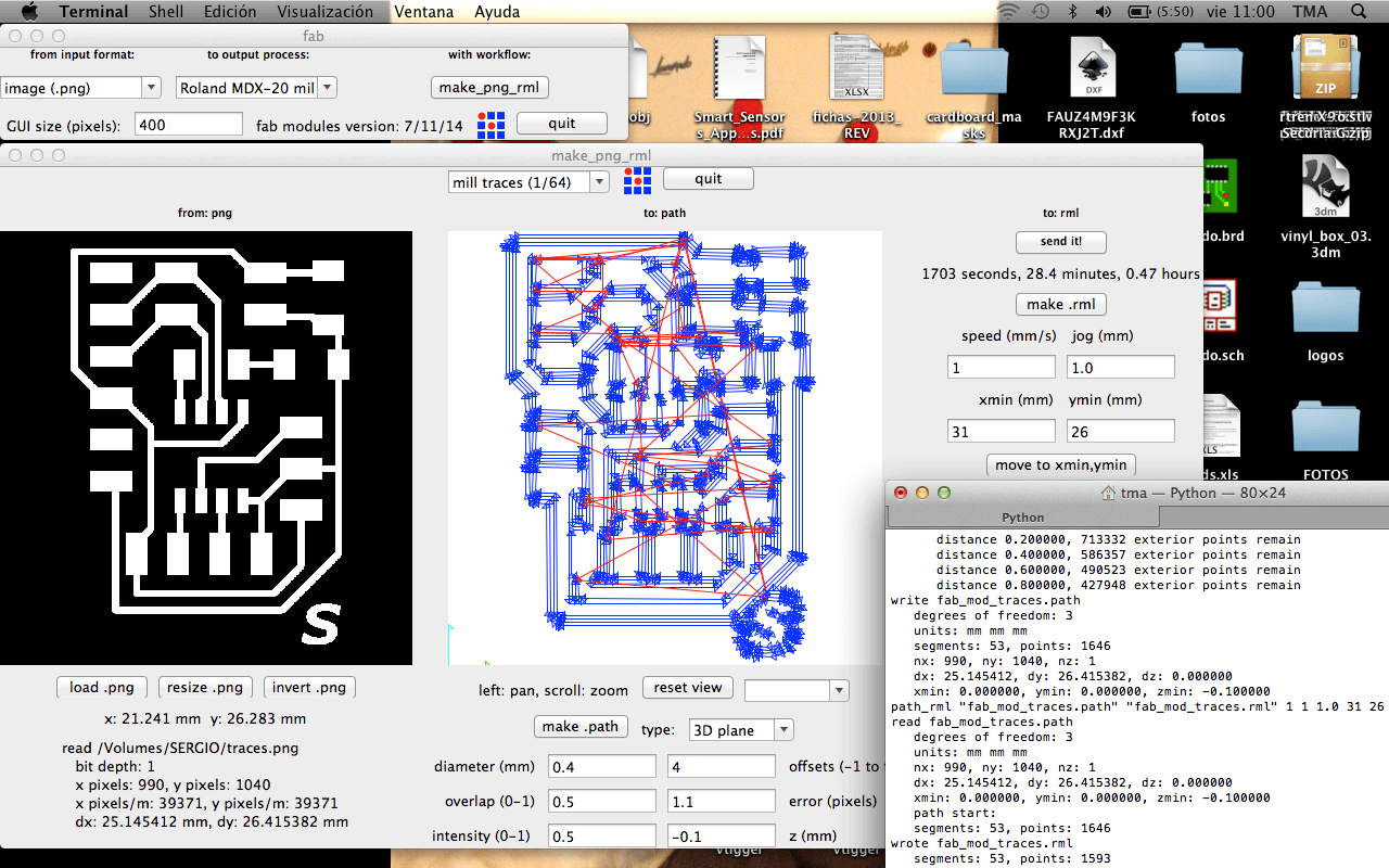
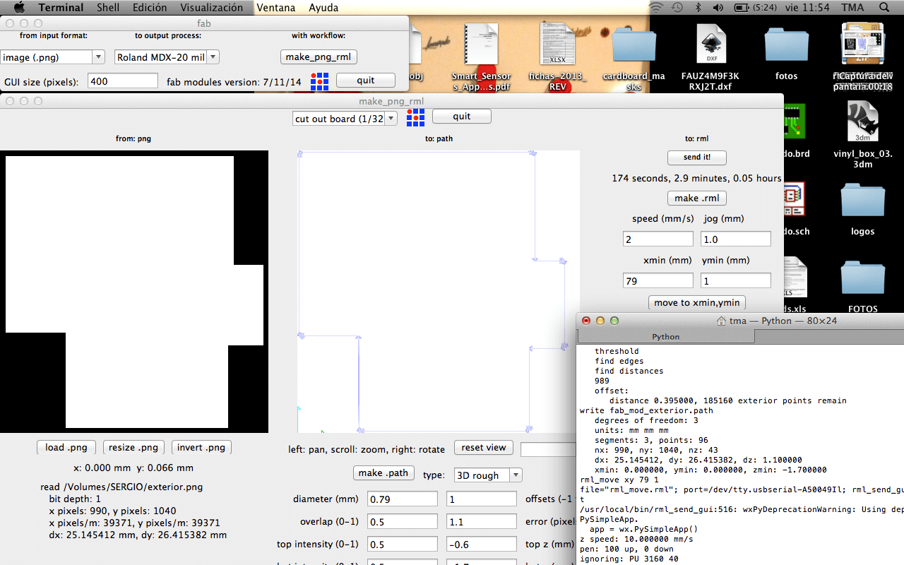
I can say I’ve managed to get good notion and workflow milling boards, but this time had a lot of trouble in the process. At first I tried to mill it in a tight space that was left on an alredy used copper plate. Measured all the dimmensions right but loaded the wrong image orientation so a part of the board was not milled. Later used another copper plate on the upper side of the bed of the Modela, but it had bad horizontal allignment and only milled down some traces. I could have adjusted just the depth of the mill but it wouldn’t be a great result, so I decide to remove all the plates and place one in the right leveled spot, and it came out nice.
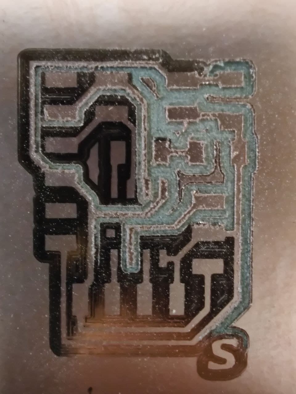
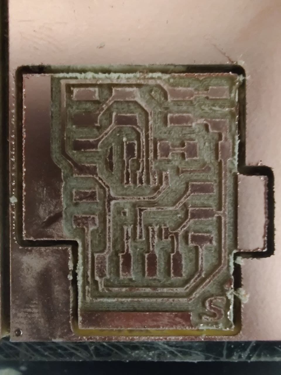
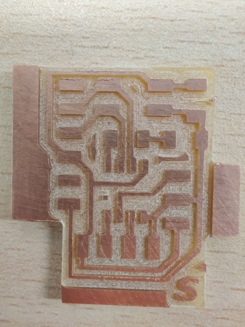
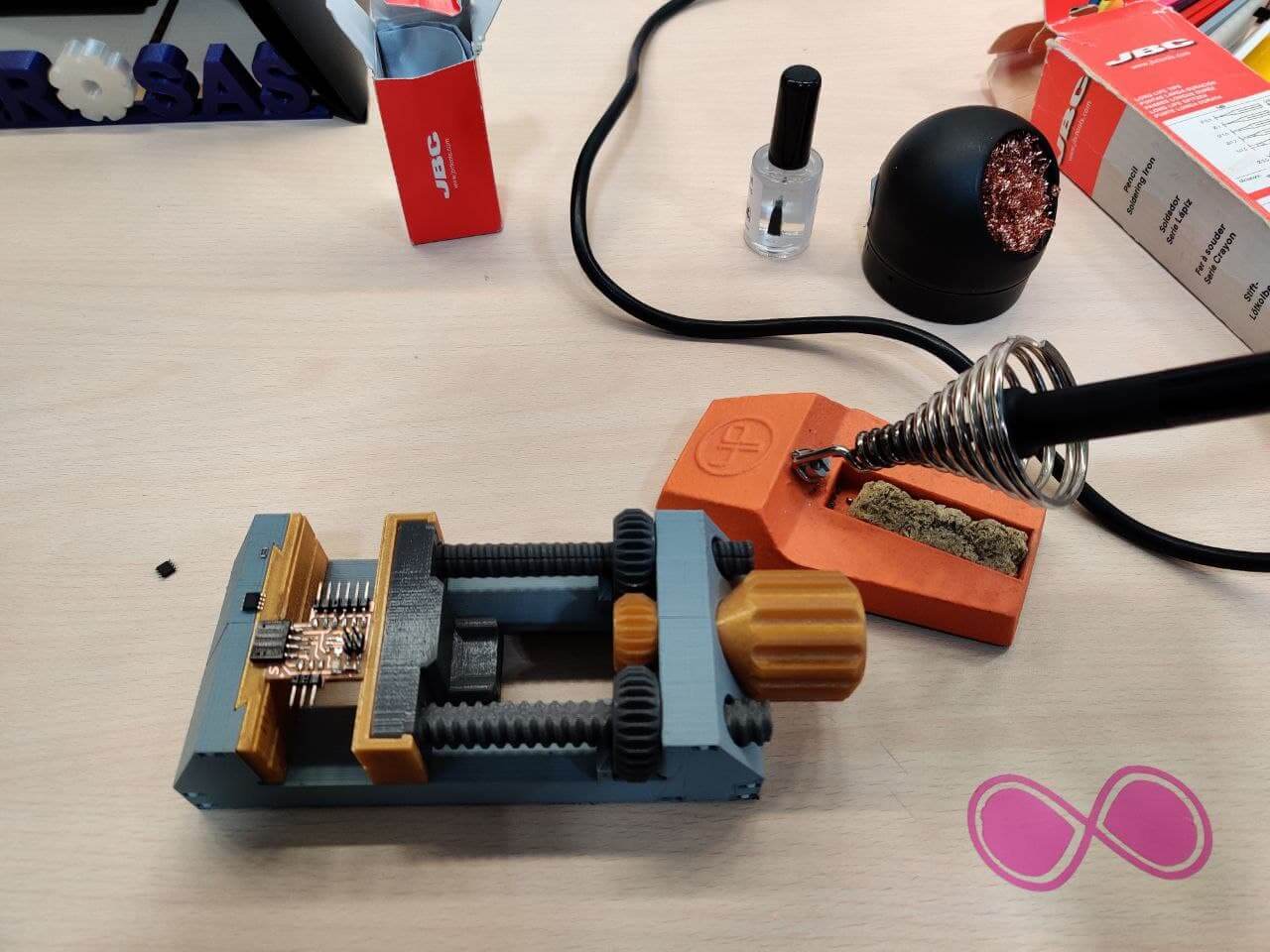
I don’t know why but every week that passes and I mill a new board, the tracks seem narrower than the week before and I find myself sweating ink to solder the components. Then once on the job, everything works fine and the solder joints come out cleaner and cleaner. I’ve had to check LED’s polarity with the multimeter, since the green line that indicates that was not very visible. Below is the list of components used from the Lab’s inventory. The final result of the soldering and the connectors with the supports was quite good. Testing the board, continuity also looks okay.
Testing⚓︎
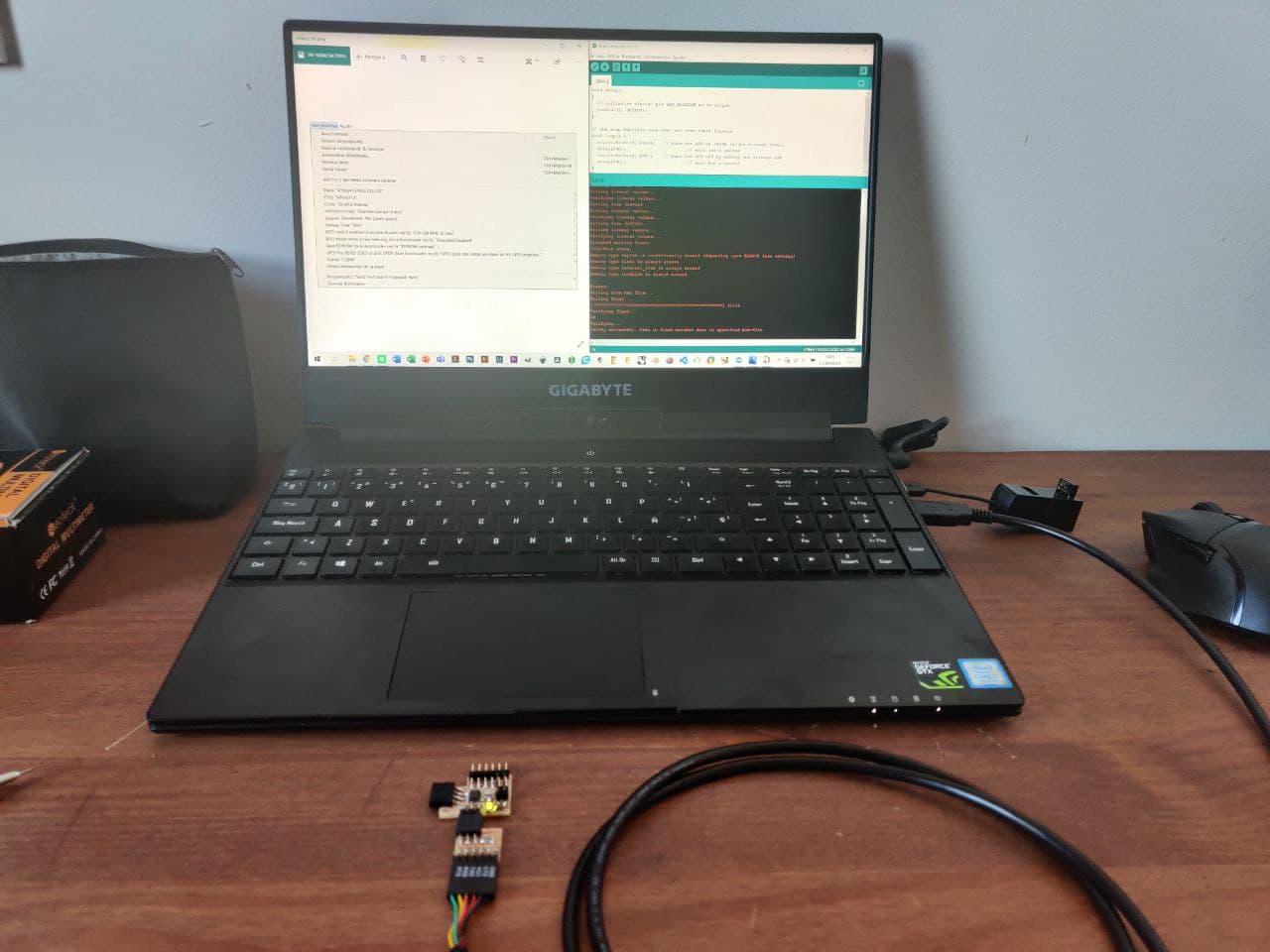
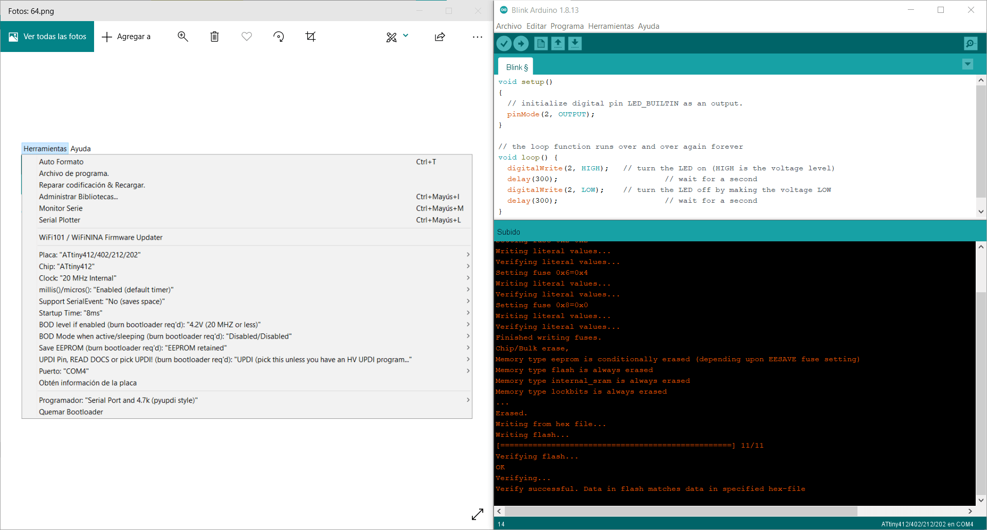
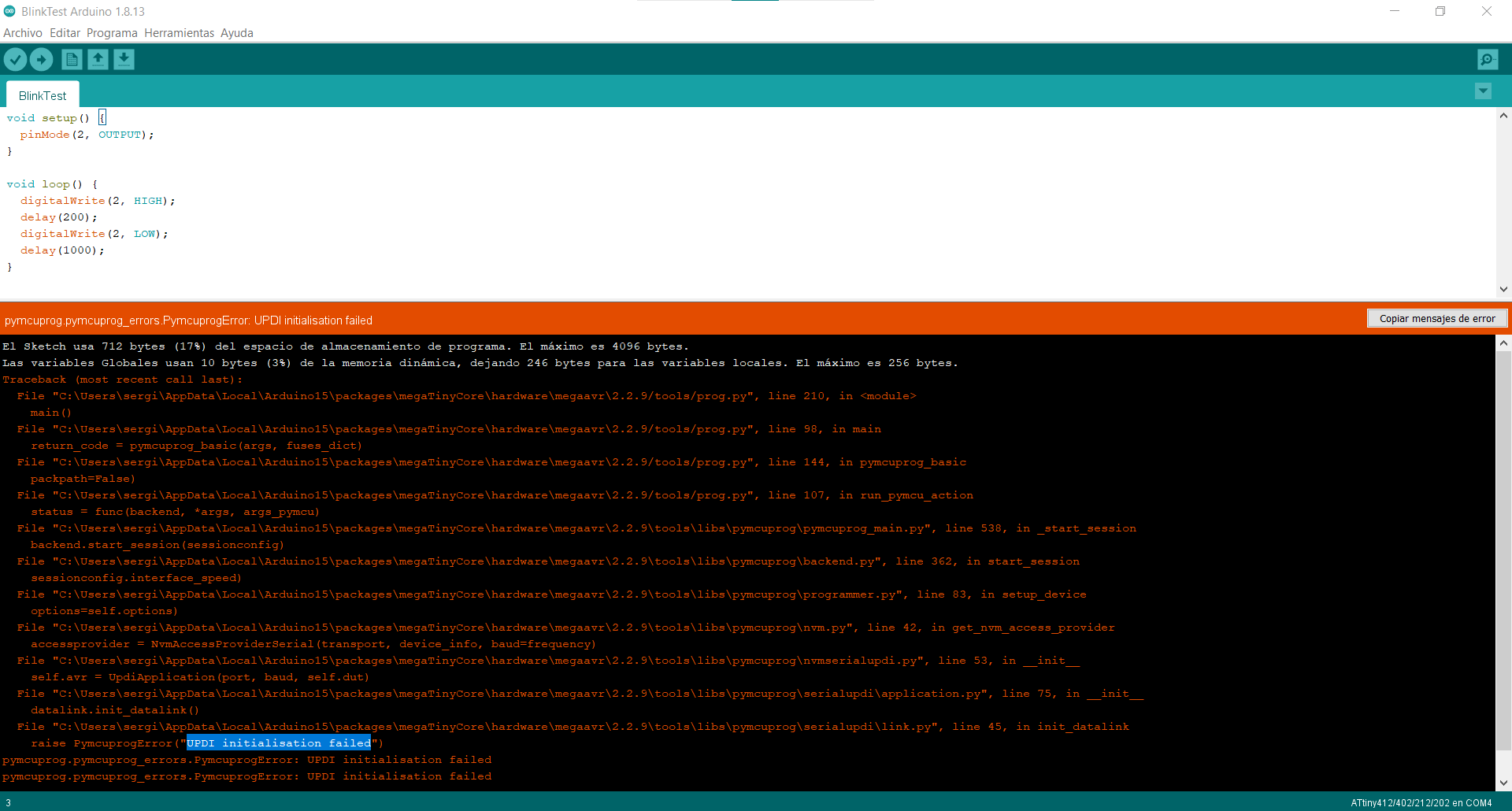
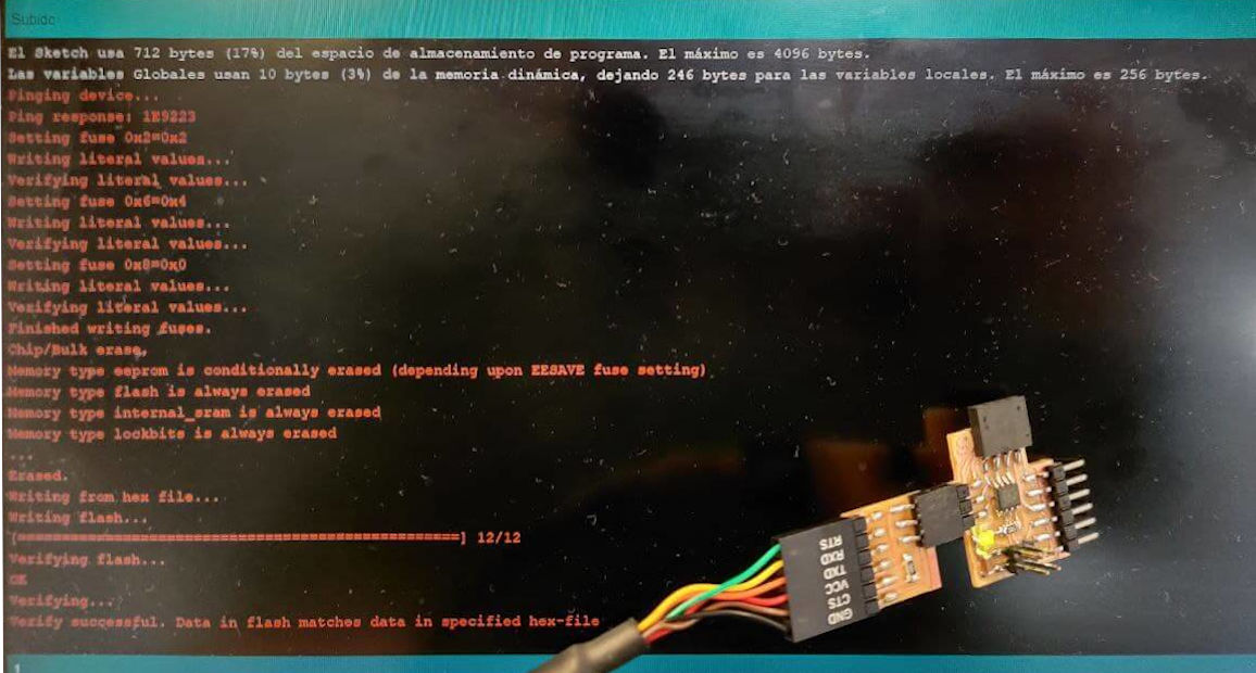
As I’ve been doing in the past, I’ve included a led in the board as a debugging utility. I just have to uplaod a simple blink to know if everything works fine. Also it lets me test the programming workflow for the processor I’m currently using. Below is the configuration I used for uploading code to the ATtiny412. It’s working fine, the led is blinking.
Ultrasonic sensor⚓︎
To get on with this sensor, I have started searching for a project which have also used this HC-SR04 ultrasonic sensor and had a functioning code. As for any spanish speaking Arduino sensor test, I found Luis Llamas testing with this sensor. It’s really usefull how detailed the process and the code is explained, it has helped me a lot.
Programming⚓︎
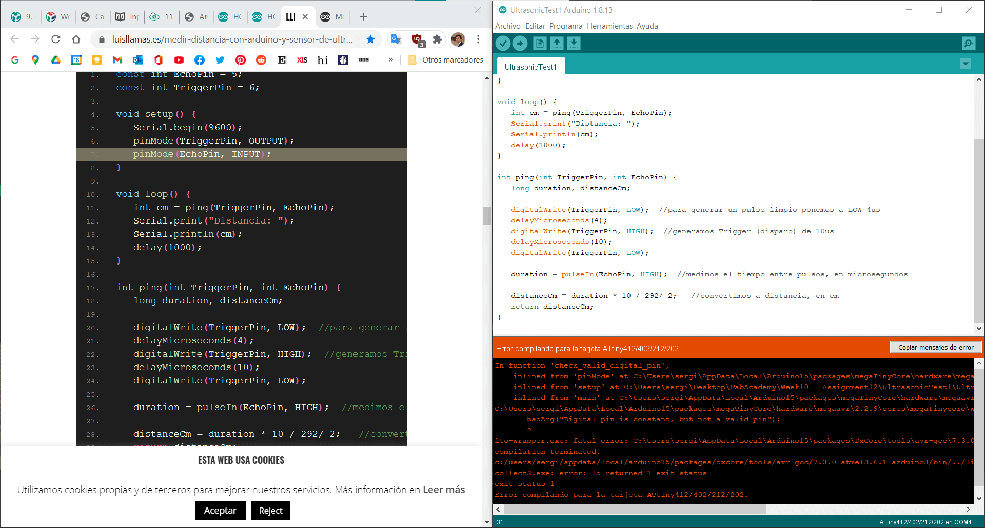
For implementing the code, I’ve had to select the correct pins for our board case and to tweak it a bit due to some errors, but now it’s working fine.
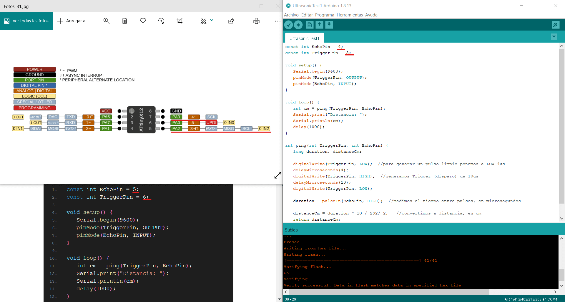
const int EchoPin = 4;
const int TriggerPin = 3;

void setup() {
    Serial.begin(9600);
    pinMode(TriggerPin, OUTPUT);
    pinMode(EchoPin, INPUT);
}

void loop() {
    int cm = ping(TriggerPin, EchoPin);
    Serial.print("Distancia: ");
    Serial.println(cm);
    delay(1000);
}

int ping(int TriggerPin, int EchoPin) { //function that calculates distance
    long duration, distanceCm;

    digitalWrite(TriggerPin, LOW);   //to generate a clean pulse set to LOW 4us
    delayMicroseconds(4);
    digitalWrite(TriggerPin, HIGH);  //generates Trigger of 10us
    delayMicroseconds(10);
    digitalWrite(TriggerPin, LOW);

    duration = pulseIn(EchoPin, HIGH);  //measures the time between pulses (us)

    distanceCm = duration * 10 / 292/ 2;   //convert to distance (cm)
    return distanceCm;
}
Measuring⚓︎
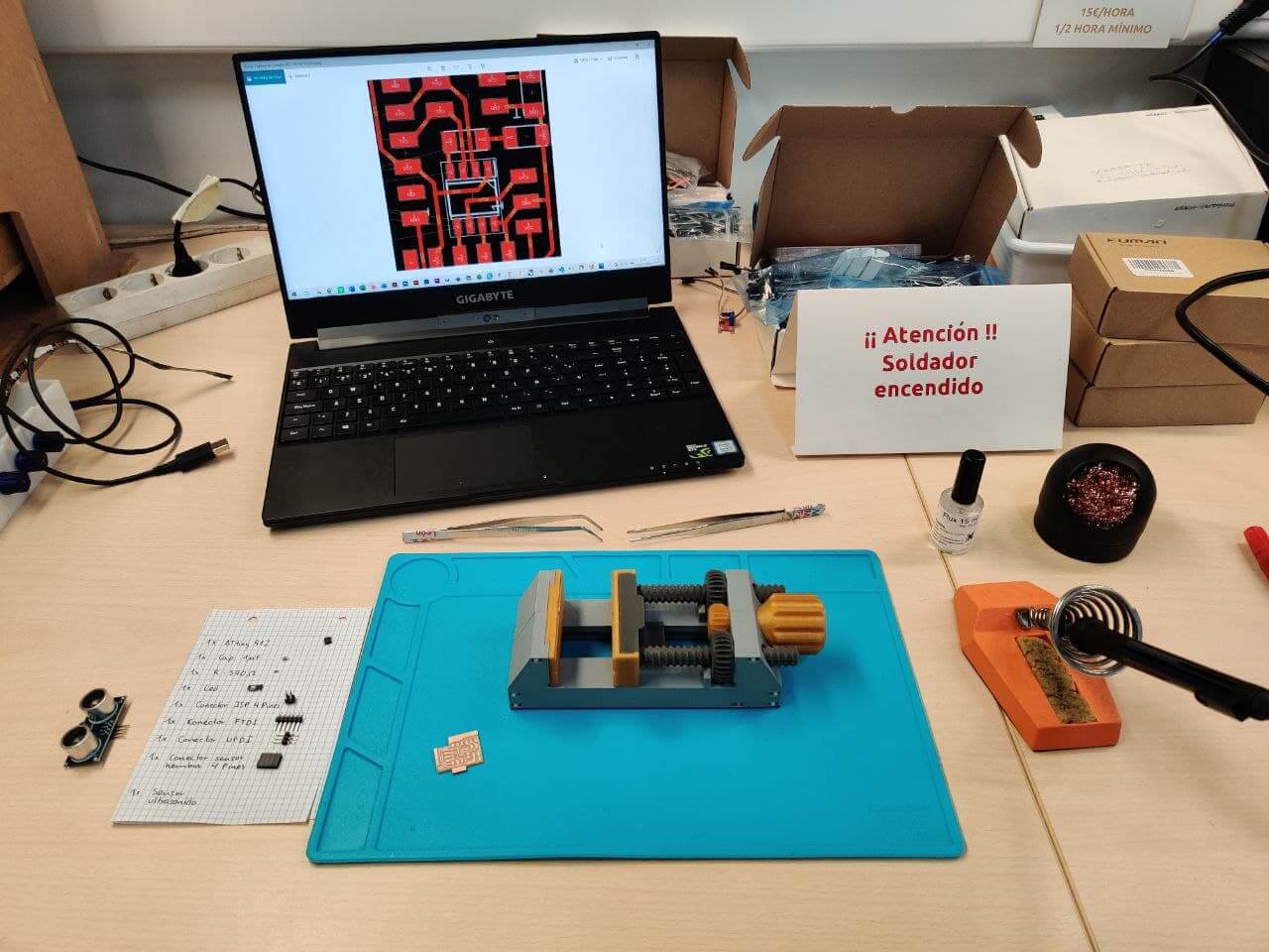
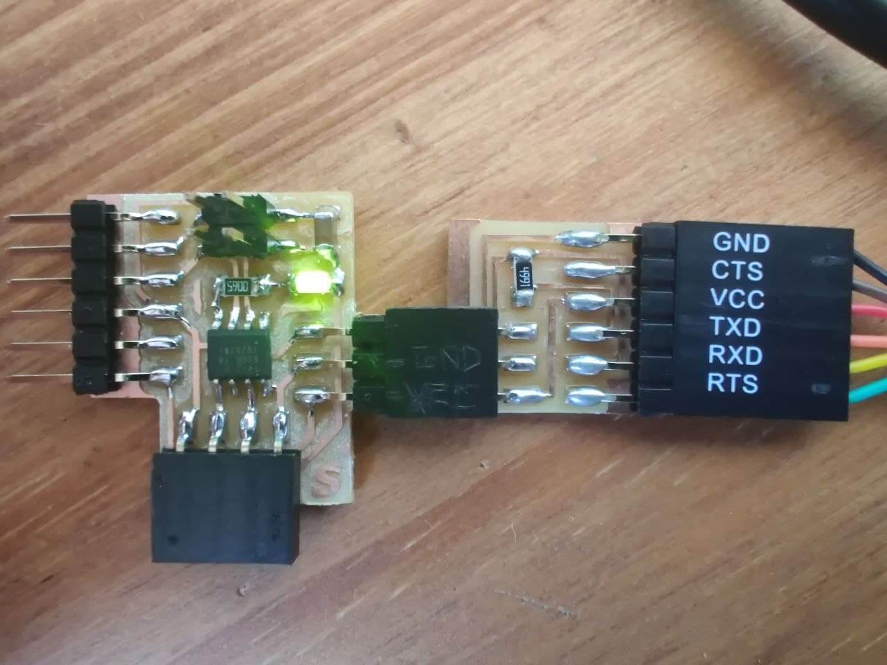
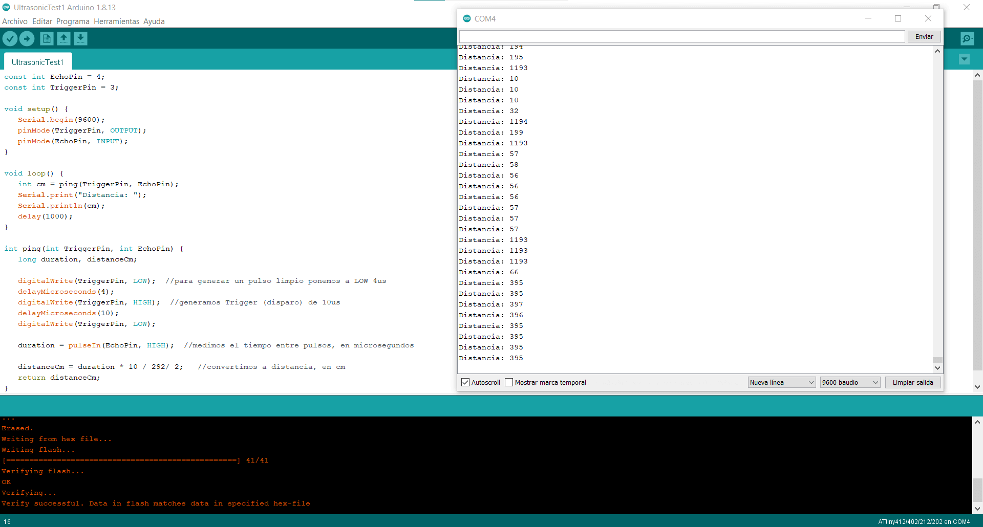
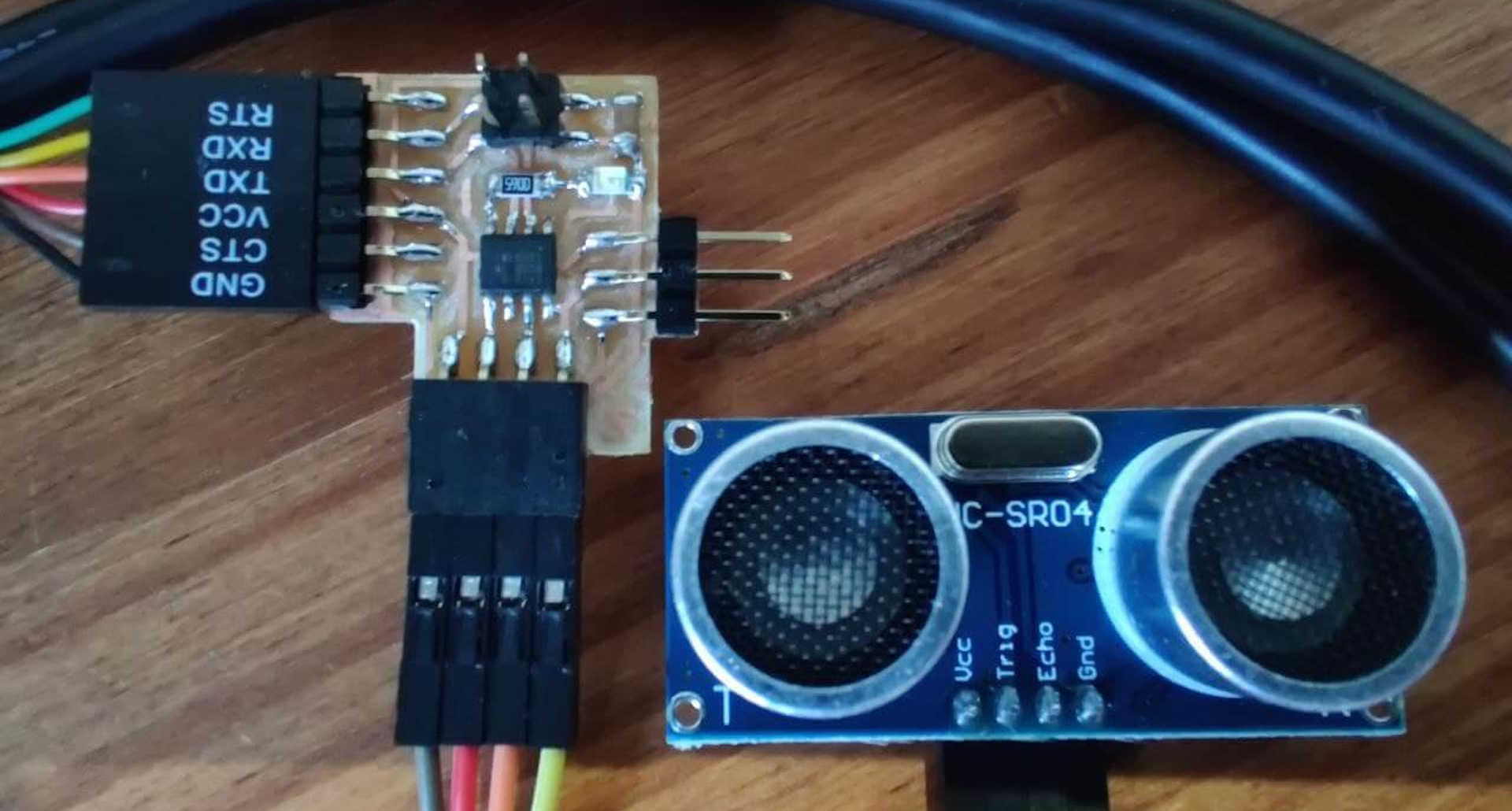
Now that the board has the code loaded, it’s time to connect the ultrasonic sensor. We’ll need male to female dupont cables, as I don’t want to connect directly the sensor to the board as I want to be able to test other inputs in the future. Once we’ve connected the sensor to the board and plug this one to through the FTDI to the computer we should start receiving data from the sensor. To see the measures we have to open the serial monitor in Arduino with the same baudrate that we set before in the code, which is 9600 bauds. The measurements are showing up and they are accurate for this kind of sensor.
Maybe you have thought that this week corked out without trouble, but in FabAcademy that’s not possible. I fried the ATtiny of the board during a test for the group assignment. I will get more in detail below. This video is a summary of all the tests I did with the sensor. From when it was working at the beggining, to where I had to replace the micro and got the senor measuring again.
Group assignment⚓︎
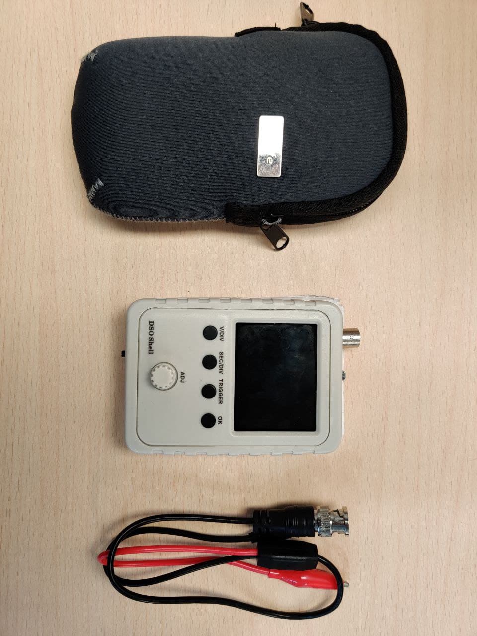
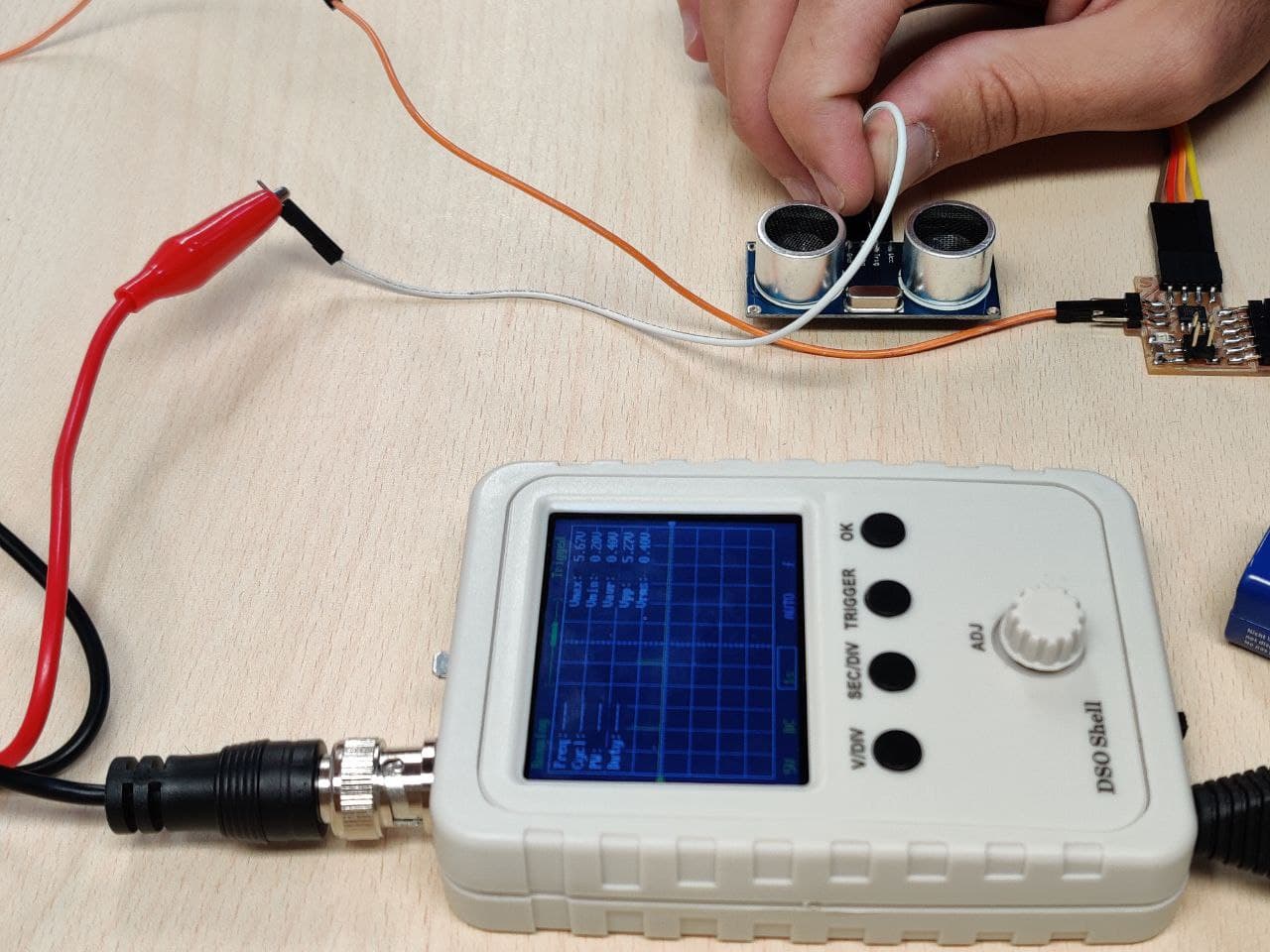
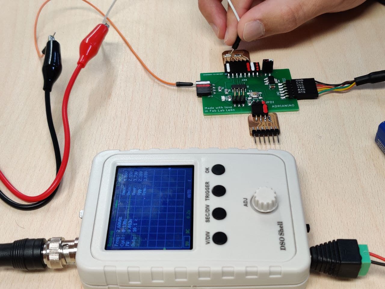
This week’s goal for the group assignment is to probe an input device(s)’s analog and digital signals. To do so, we’ll need an oscilloscope or any other electrical data analyzer. I will be using this small one that we have at the lab. We are also going to need a sensor that emits an analog output, since the ultrasound sensor does it digitally. For this case, my instructor Adrian has kindly left me his Adrianino and a board with a phototransistor (since he has done me the favor, I’ll take the opportunity to advertise his work 
 )
)
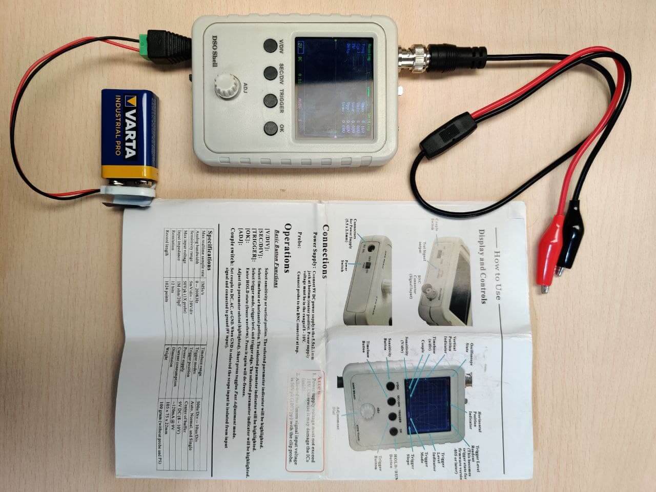
After reading a bit the configuration and characteristics sheet of the oscilloscope, I have turned it on to analize the devices signal. It is important to adjust with the rotary wheel the measurement scale to which we want it to represent the data, and the interval in which we want it to do so. If these values are not correctly determined, we may be reading the signal but not seeing it represented on the screen.
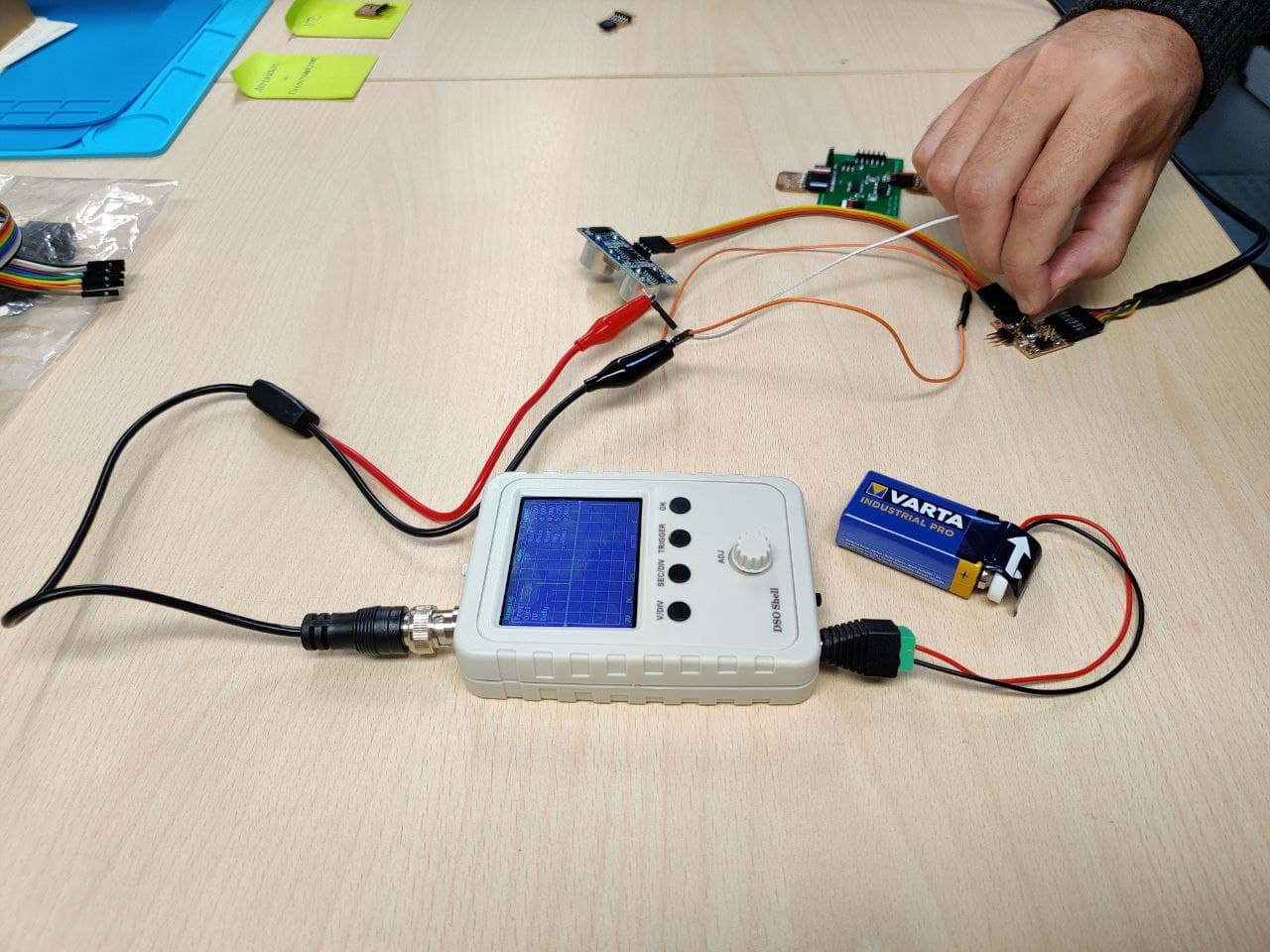
I have started by measuring the ultrasound sensor. As expected, being a digital signal the graph that appears is linear in jumps. Either it has a signal, or it doesn’t. We observe a pulse each time the sensor sends a trigger or an echo. On the contrary, the phototransistor sends an analog signal, which translates into a progressive curve depending on the values it is receiving. If we modify the light little by little, we see how the value curve is progressively changing.
Failure
In the photos I have taken for documentation, the data on the oscilloscope screen is barely visible. I was under one of the light bulbs on the work table and the screen comes out with a lot of reflection and very little light, especially the data that is displayed in yellow. I didn’t realize it until I was documenting it. Luckily in the video shown at the end of the page it’s can be seen a bit better.
At some point during the measurements, I probalby touched two pins of my board with one of the ends of the dupont cables, making a short in the micro. At first I thought that the ultrasonic sensor had broken or that some track from the board would have ripped apart, but when I have connected it to the computer to reload the code, the Arduino console has shown UPDI initialization failed, which normally means electrical failure.
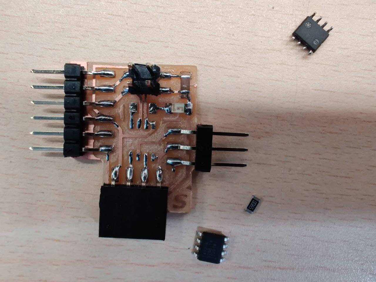
To change the ATtiny412 I used the heat gun and some tweezers, and it was surprisingly easy. After taking another 412 and soldering it, the board is back to life. To check if it works again I have used the classic “blink for debugging”.
This video is a summary of all the testing done with the oscilloscope in both sensors. Thankfully, the yellow data line graph it’s a little more visible in the video than in the photos.
Files⚓︎
- Schematic design from Eagle of the Input board (
.sch): file - Board design from Eagle of the Input board (
.brd): file - Traces of the Input board (
.png): file - Exterior of the Input board (
.png): file - Arduino code V1 for ultrasonic sensor with the Input board (
.ino): file - Arduino code V2 for ultrasonic sensor with the Input board (
.ino): file