17. Machine Design
Time to finish up the Rube Goldberg Machine, and get everything working together!
Learning outcomes - Work and communicate effectively in a team and independently - Design, plan and build a system - Analyse and solve technical problems - Recognise opportunities for improvements in the design
Have you? - Explained your individual contribution to this project on your own website
Background
See last week for the mechanical part of the conveyor belt and how it ties in to the broader Rube Goldberg machine. Basically just need to automate it. A lot of what I discuss below is also covered in my [input]http://fabacademy.org/2019/labs/dassault/students/alexander-demers/assignments/week11/ and output device weeks, but I’ll chat a bit here!
Design
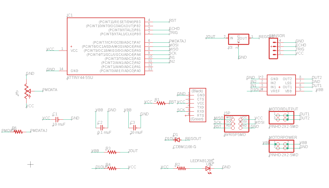
First, I wanted to use a Hall magnetic field sensor to trigger the conveyor, since that is what others in the group were thinking to use. But the distance/motion sensor makes more sense for a stand alone conveyor belt. So the board and schematic originally used:
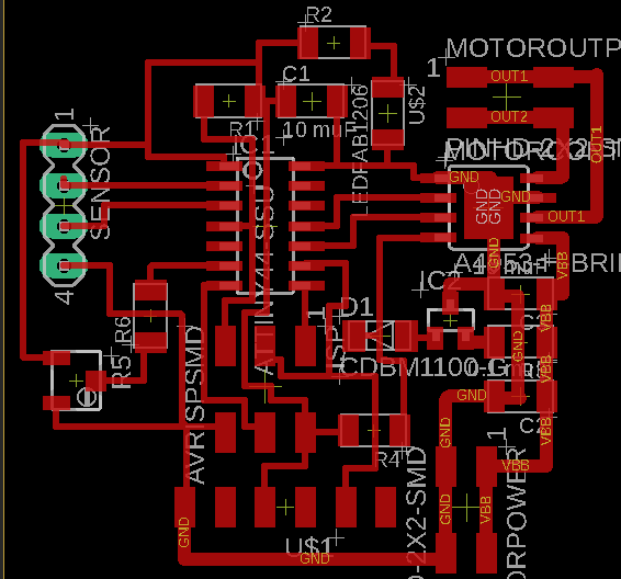
The real board, in all of it’s glory!
In output devices week I talked a little bit about some problems I had with getting the motor to work, due to both outputs from the h-bridge being high despite only in 1 being high, so we cut one and tied it to ground. That meant from the programming the motor could only run in one direction, but we could always flip the 2x2 header leading to it around to change the direction. I also want to rehash the issues with the digitalWrite vs the analogWrite, where the analog appears to work better. OK!
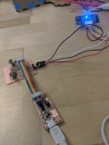
Here’s a video of the motor running from the board:
Cool. So now we have the working motion sensor, and we can redo all of the programming so they work together.
Code
Speaking of, here it is!
int ledpin = 7;
int in1 = 3;
int in2 = 2;
int trig = 10;
int echo = 9;
int test = 0;
long duration;
int distance;


void setup() {
  // put your setup code here, to run once:

pinMode(ledpin, OUTPUT);
pinMode(in1, OUTPUT);
pinMode(in2, OUTPUT);
pinMode(trig, OUTPUT);
pinMode(echo, INPUT);
analogWrite(in1, 0);
analogWrite(in2, 0);
digitalWrite(ledpin, HIGH);


}

void loop() {
  // put your main code here, to run repeatedly:
while (test = 0) {

  digitalWrite(ledpin, HIGH);
  delay(10000);
  test = 1;
}


digitalWrite(ledpin, LOW);
analogWrite(in1, 0);
analogWrite(in2, 0);
  digitalWrite(trig, LOW);
  delayMicroseconds(2);

  // Sets the trigPin on HIGH state for 10 micro seconds
  digitalWrite(trig, HIGH);
  delayMicroseconds(10);


  // Reads the echoPin, returns the sound wave travel time in microseconds
  duration = pulseIn(echo, HIGH);
  digitalWrite(trig, LOW);


  // Calculating the distance
  distance= duration*0.034/2;
if (distance < 10) {

  digitalWrite(ledpin,HIGH);
  analogWrite(in1, 0);
  analogWrite(in2, 240);
  delay(30000);
  analogWrite(in2, 0);

}


}
Let’s put the whole together!
Video
The machine running, automated like, from the ball triggering the motion sensor:
And the Rube Goldberg machine running (somewhat successfully!):
Files
Other design files are available in mentioned weeks.
Summary
I got my conveyor belt to run automated based on a ball triggering it! For the actual Rube Goldberg demonstration it wasn’t quite tuned in, but as seen in that video it does work now! Cool! Moving forward, I want to emphasize my work on the conveyor belt so that I can make that. Seriously, students love that thing and it will be a great piece to show off in the school.