| This week | |
|---|---|
| Presentation Output Devices | http://academy.cba.mit.edu/classes/output_devices/index.html |
| video of the review (Input Devices) | http://fab.academany.org/2018/lectures/fab-20180411.html |
| video of the lecture | http://fab.academany.org/2018/lectures/fab-20180411.html |
| recitation: making machines | https://github.com/fellesverkstedet/fabricatable-machines |
| Assignment | Used software | Files/Downloads/links |
|---|---|---|
| Group Assignment | measure the power consumption of an output device | http://fab.academany.org/2018/labs/fablabamsterdam/outputdevices/index.html |
| oled board | kicad | oled1.zip |
| attiny code | arduino-ide | i2c-lcd.ino |
Board
Learned a lot this week! And last week
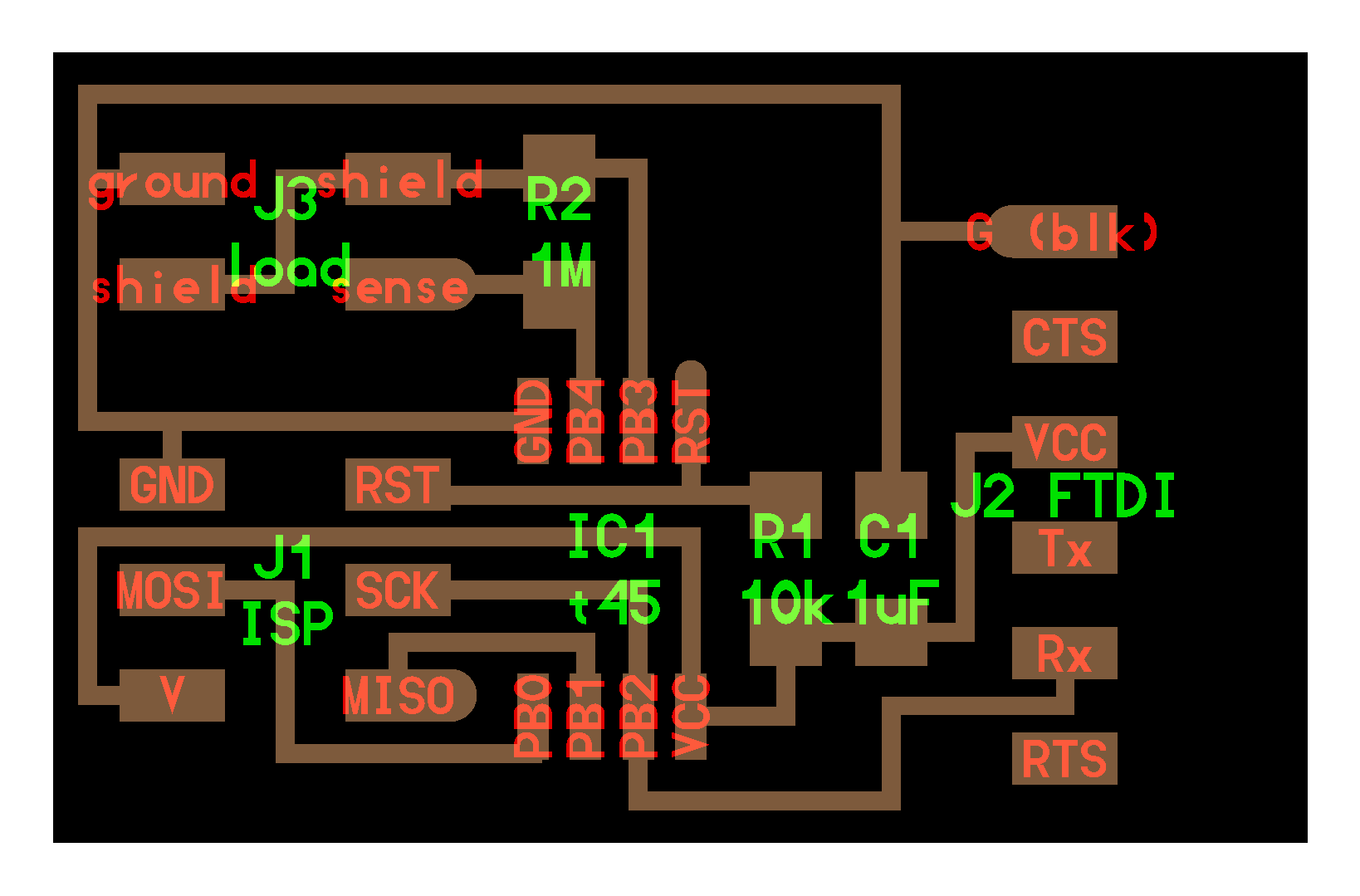
In kicad i made a lot of progress. I made my fist footprints and used the symbol library editor for getting the pins of the hc-sr04 in kicad. And then i also figured out how to use the 0ohm resistors in kicad when working with traces.
- make your scheme
- also including editing symbols and footprints if needed.
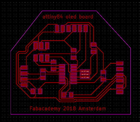
- place the components in the pcb editor.
Then the routing. I used Freeroute, see week about electronics design, but now i decided to do the traces myself. At first i made the gnd and vcc connecting as much as possible components. Then going to the other traces. As soon as i discovered a route that needed a 0ohm, i went back to eescheme, plutting the 0ohm in there. And updating the pcb editor from schematic (under Tools). Then the new 0ohm is put on the place i want and continou tracing. I really loved the end result.
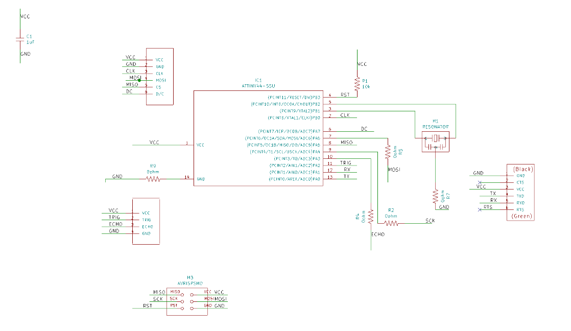
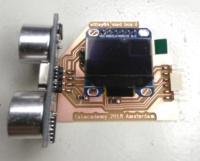
About the components: I used a oled screen i had around somewhere. It is a 0.96” IIC SPI Serial 128X64 OLED LCD Display SSD1306. And it’s an old version. When you now look for the oled display, it are all boards that you can program with 12c and spi.
###I2C
I2C is an acronym for “Inter-Integrated Circuit”. In the late 1970s, Philips’ semiconductor division (now NXP) saw the need for simplifying and standardising the data lines that travel between various integrated circuits in their products. Their solution was the I2C bus. This reduced the number of wires to two (SDA – data, and SCL – clock).
###SPI
Serial Peripheral Interface (SPI) is a synchronous serial data protocol used by microcontrollers for communicating with one or more peripheral devices quickly over short distances. It can also be used for communication between two microcontrollers.
With an SPI connection there is always one master device (usually a microcontroller) which controls the peripheral devices. Typically there are three lines common to all the devices:
MISO (Master In Slave Out) - The Slave line for sending data to the master,
MOSI (Master Out Slave In) - The Master line for sending data to the peripherals,
SCK (Serial Clock) - The clock pulses which synchronize data transmission generated by the master
and one line specific for every device:
SS (Slave Select) - the pin on each device that the master can use to enable and disable specific devices.
When a device’s Slave Select pin is low, it communicates with the master. When it’s high, it ignores the master. This allows you to have multiple SPI devices sharing the same MISO, MOSI, and CLK lines. </I>
Anyway: i fugured out this old oled screen didn’t use I2C when i was checking if the oled actually worked. I used a ordinary arduino UNO for that. I2C didn’t work, SPI did. So i had to program the newly made board with SPI. As read above, it uses more pins, but that wasn’t a problem with the Attiny84 that is on the board.

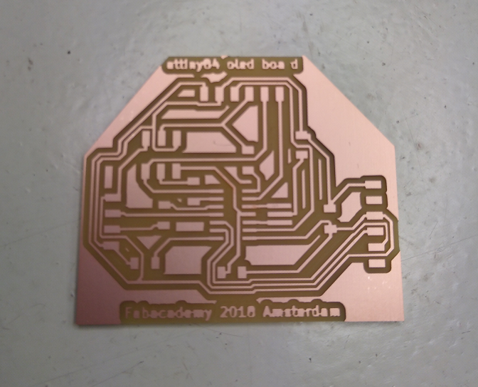
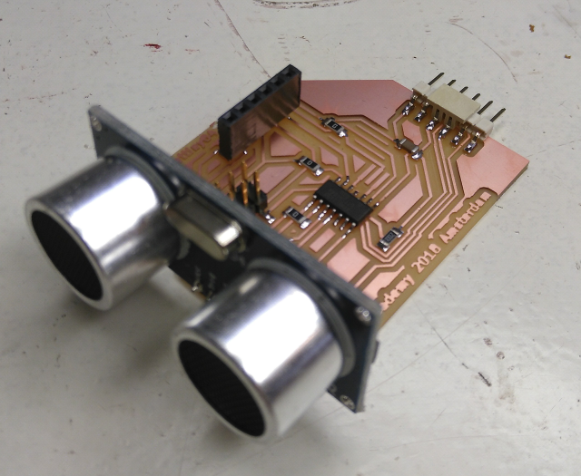
Back to the board. Milling and soldering the board went smooth. And the board looked nice!
So far, so good…
Then the problems starting!
- I forgot to solder the resonator (see above in the photo’s). That problem was easy to solve.
- After burning the bootloader i couldn’t programm the board anymore. Any communication with the board failed. This problem was harder to solve because i didn’t understand what the problem was. After a couple of hours, i solved the problem by using the heatgun to replace the attiny84. This didn’t solve the problem, that was the same after burning the bootloader. After a lot of debugging (and time) Emma found the problem. In the schematic i connected the resonator to the wrong pins.
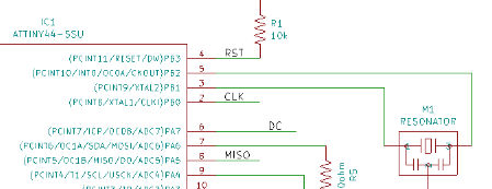
The resonator should be connected to xtal1 and xtal2, so pin 2 + 3. And the CLK to pin 5.
By burning the bootloader after the next reboot the attiny84 is looking for the clock on pin 2+3 and that one is not there :( So no clock means more or less dead.
Another board (attiny85)
I lost a lot of time debugging and understanding what i did wrong on my board. So the last day i tried to fullfill this weeks assignment in the short time left.
So i milled another board to experiment with. Because while searching the internet about attiny and oled display a lot of time the tiny85 was mentioned as an example, i milled a basic attiny85 board from the fabacademy website. Then i used this page on instructables to get the display going.
My arduino-ide library structure was a mess in the mean time. So i downloaded the latest arduino-ide from arduino.cc. And immediately deleted the liquidcrystal libraries and installed new liquidcrystal mentioned on the instructables site. I also reinstalled the TinyWireM libraries.
The NewLiquidCrystal library has to be modified to make it work with the ATTINY chips. Modify the following file accordingly.

Find the following file I2CIO.cpp and make the modification below:
Line 33 replace with:

#if (ARDUINO > 100)

Line 34 “#include <../Wire/Wire.h>” replace with

#if defined(__AVR_ATtiny84__) || (__AVR_ATtiny2313__) || defined (__AVR_ATtiny85__)

#include "TinyWireM.h" // include this if ATtiny84 or ATtiny85 or ATtiny2313

#define Wire TinyWireM

#else

#include "Wire.h" // original lib include

#endif
I located the file and did the replacement.
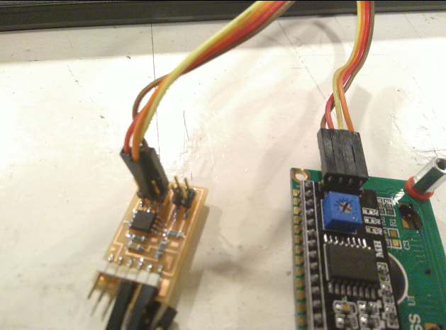
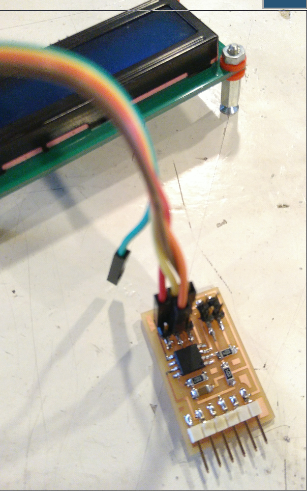
I then wired the attiny85 and the i2c module for the LCD screen:
VCC and GND from the ISP headers to the i2c module
Pin5 –> LCD Sda
Pin7 –> LCD Scl
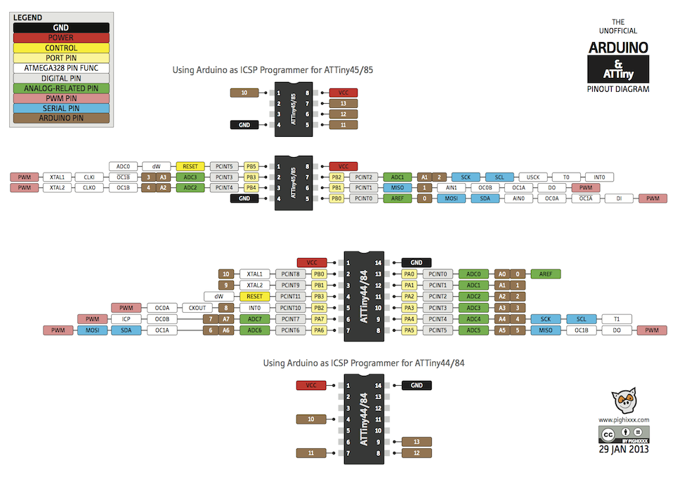
So with my board it are the SPI pins MOSI and SCK
PB0 = MOSI PB2 = SCK/SCL
Then i uploaded the code to the ATTINY85.
Silly me, because i just wired those pins to the lcd board. So after disconnecting those, i took the ISP cable, uploaded the code and rewired for the LCD.
#include <LiquidCrystal.I2C.h>

#include <usi_twi_master.h>

#include <tinywirem.h>

//usr

//To wire your Lcd I2C Display to your ATtiny85, connect the following pins :

//

//ATtiny85 Pin1 –> NC

//ATtiny85 Pin2 –> NC

//ATtiny85 Pin3 –> NC

//ATtiny85 Pin4 –> Ground

//ATtiny85 Pin5 –> LCD Sda

//ATtiny85 Pin6 –> NC

//ATtiny85 Pin7 –> LCD Scl

//ATtiny85 Pin8 –> +5V

//

LiquidCrystal_I2C lcd(0x27, 2, 1, 0, 4, 5, 6, 7, 3, POSITIVE);

void setup()

{

lcd.begin(16, 2);

//3 flash introduction

for (int i = 0; i< 3; i++)

{

lcd.backlight();

delay(150);

lcd.noBacklight();

delay(150);

}

lcd.backlight();

lcd.setCursor(2, 0);

lcd.print("Instructables");

lcd.setCursor(6, 1);

lcd.print("...");

}

void loop()

{

}
Then i modified the code to print
lcd.print("Distance in cm:");
lcd.print((distance) "cm");
and realized i needed more pins to connect a hc-sr04 distance sensor but that would be a problem because the amount of broken out pins from the attiny85.
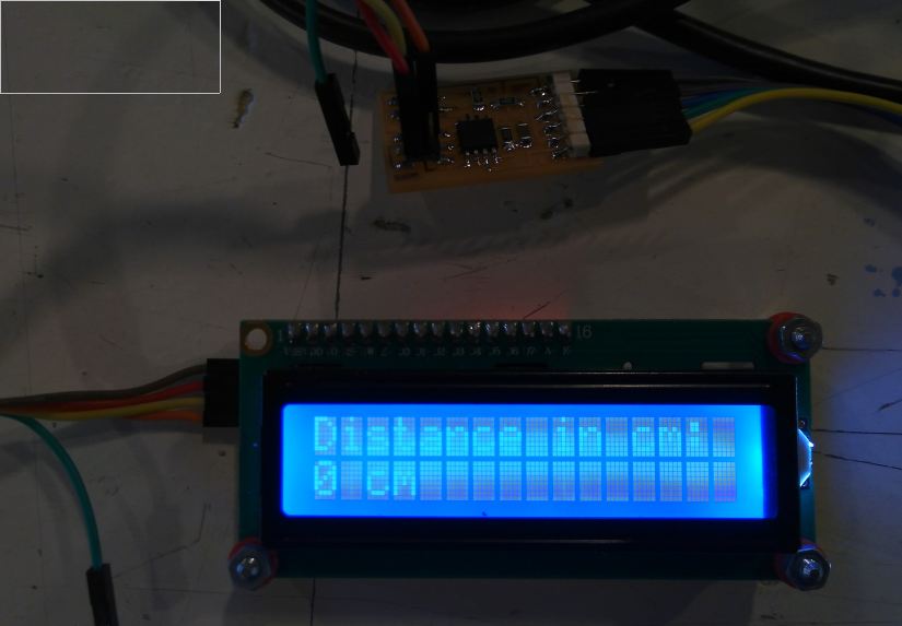
So for this week this is it. It’s “almost” printing someting meaningfull but i learned a lot of electronics arduino-ide debugging.