Computer Controlled Machining.
Concept
Computer Numerical Controlled (CNC) machine, compared to previously used 3D printer, is a
The aim of this session is to make something big. I intended to make a standing desk for a while now and sicne the lab didn't have one but normal sitting desks, I decided to make an extension for the already existing desks.
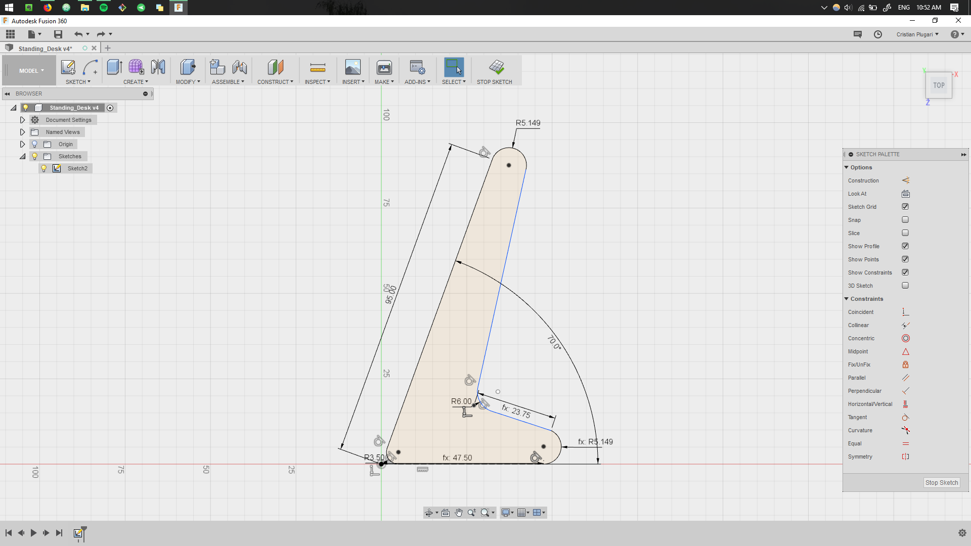
Sketching.
After reviewing some existing CNC standing desks, some sketches were made that would represent the baseline of the design.
.jpg)
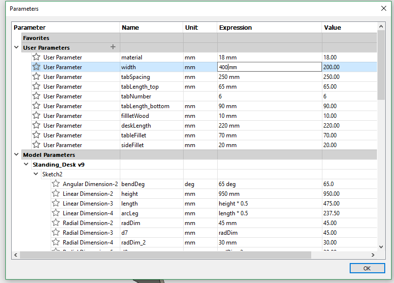
Parametric Design.
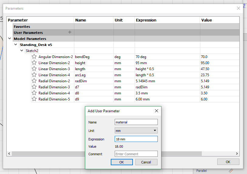
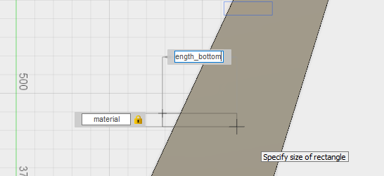
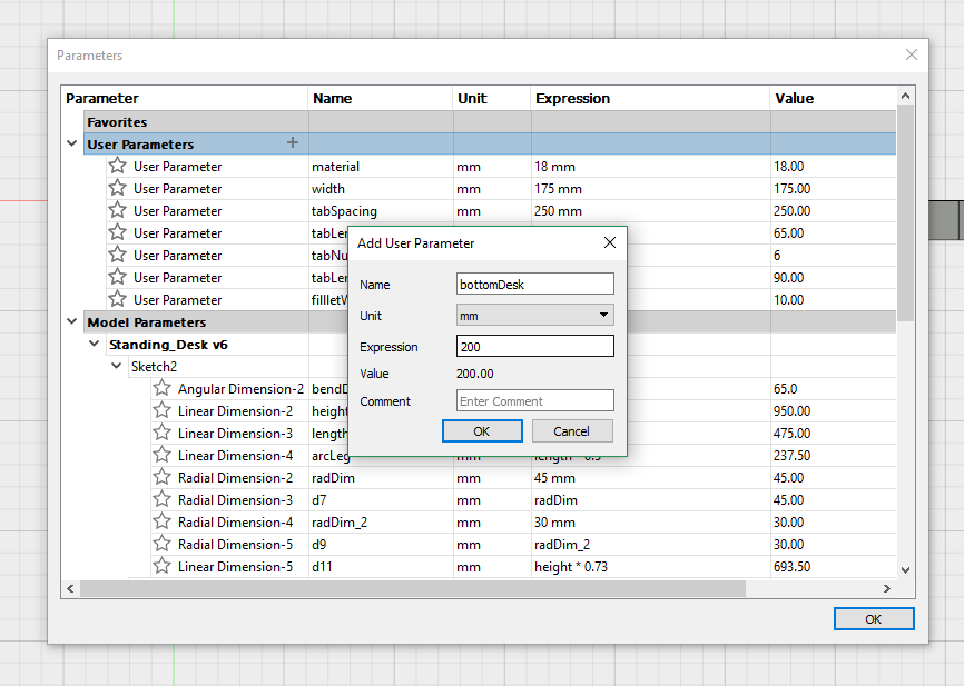
The design was created using the Fusion 360 software with the goal in mind to have a parametric design. The parametric design would allow scalability of the desk to suit different heights as well as widhts.
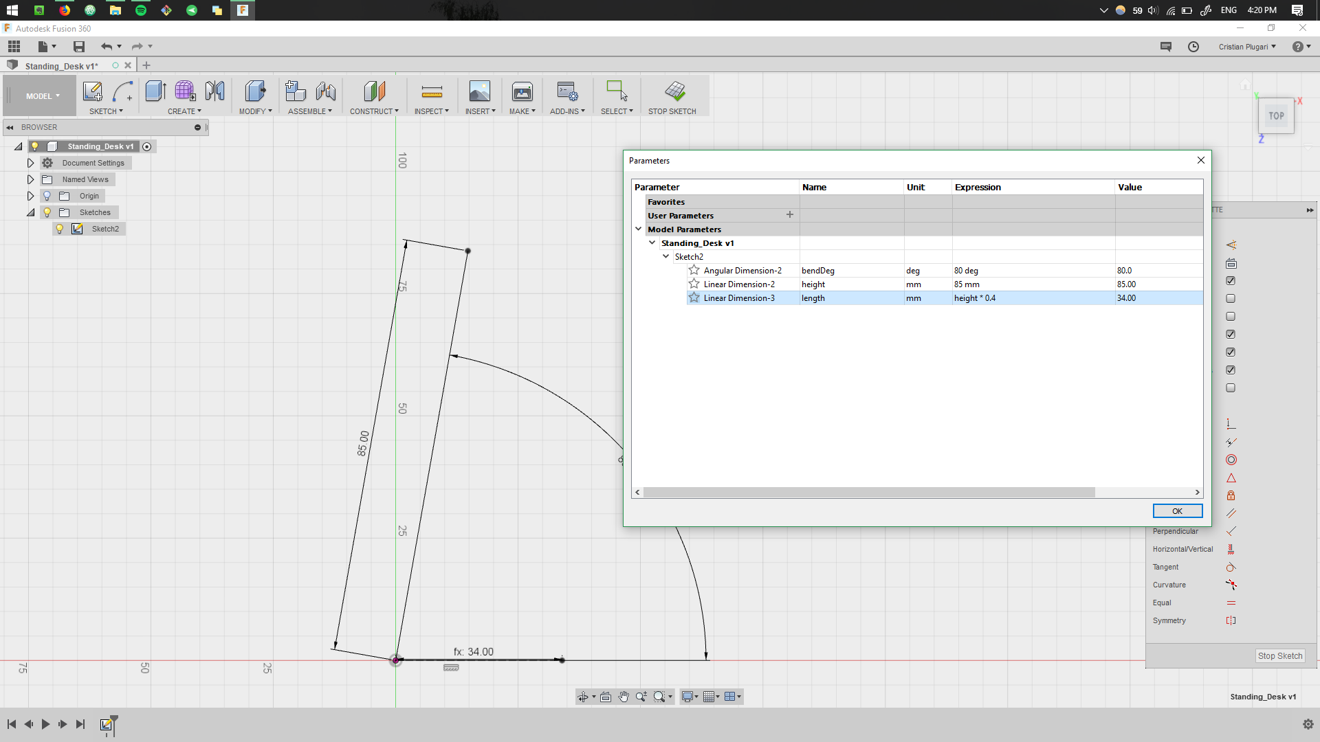
This step is quite crytical, defining the parametric values during the first sketches. Having a good parametric design, will allow easy changes during the later design process. More details about parametric design can be found in Computer Controlled Cutting week.
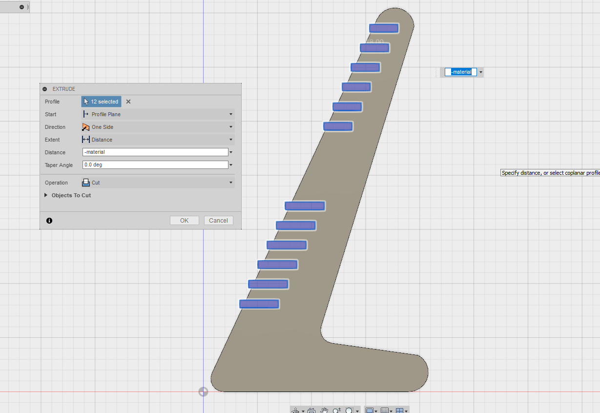
Once we are comfortable with the sizes, the design is extruded into 3D object.
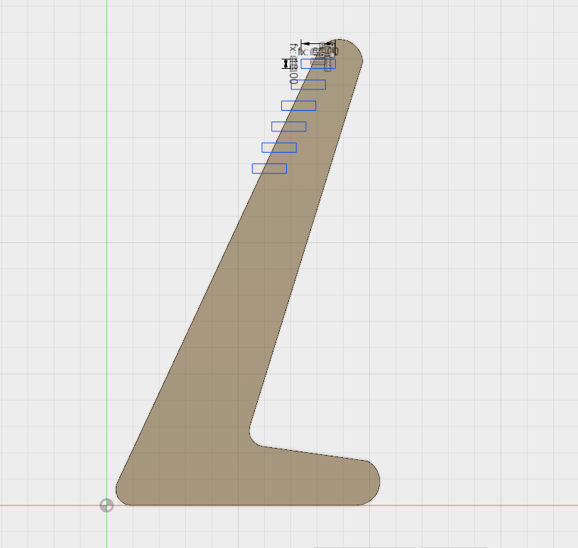
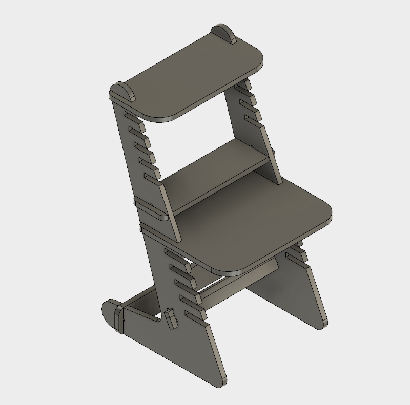
Assembling the 3D Model.
Next stage include a continuous design, to fit all the parts together.
These cuts are made intentionally. Here the user will be able to adjust the height and position of the desk.
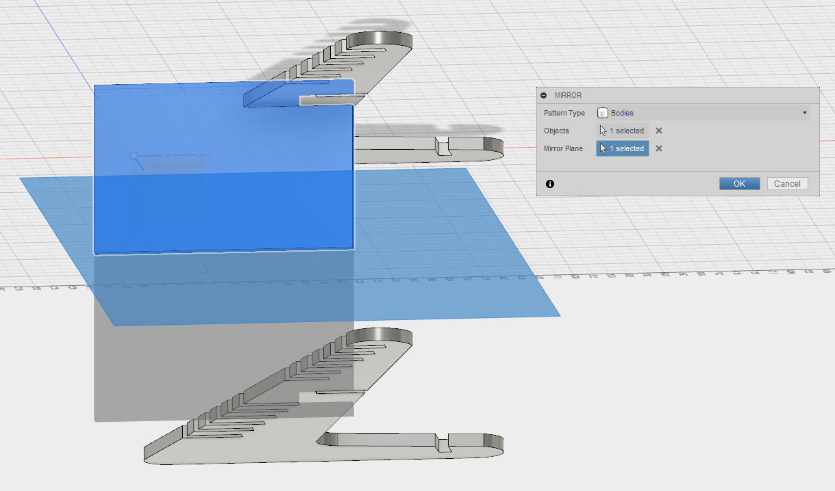
The size of the desk is also parametrically designed, so that the user can easily adjust how wide the surface are is.
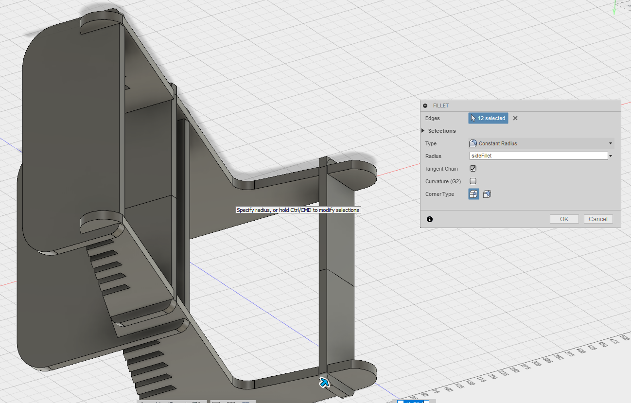
To allow smooth corners and a finer look, fillets are added.
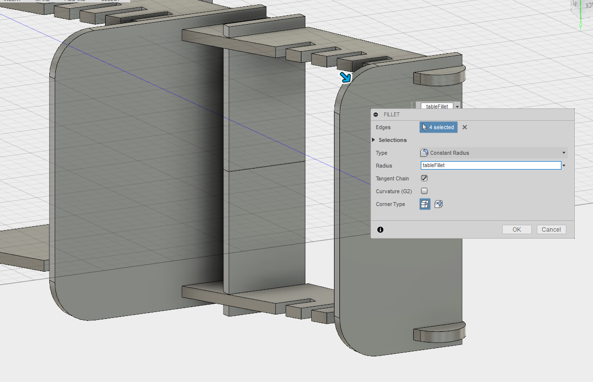
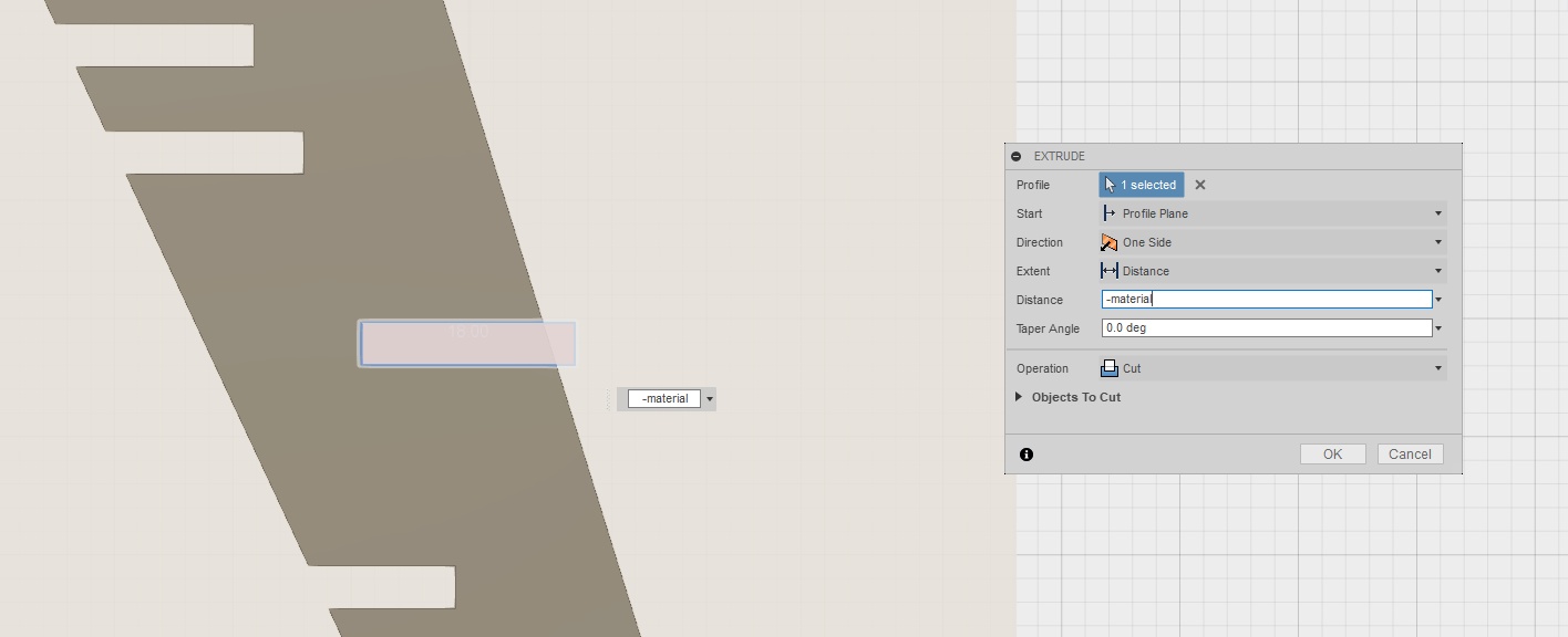
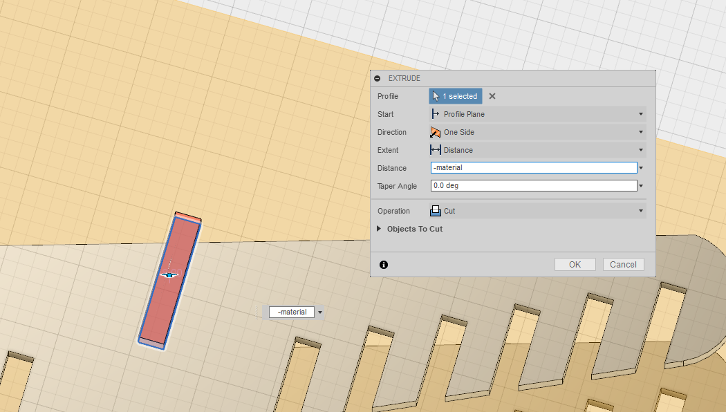
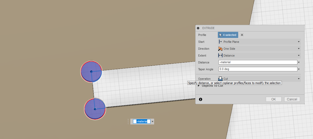
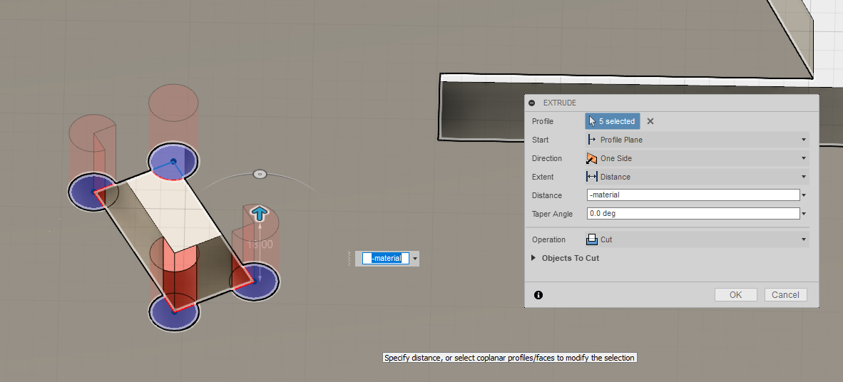
Press Fit.
In order to allow a press fit design, wherever the pieces have to fit one into the other,
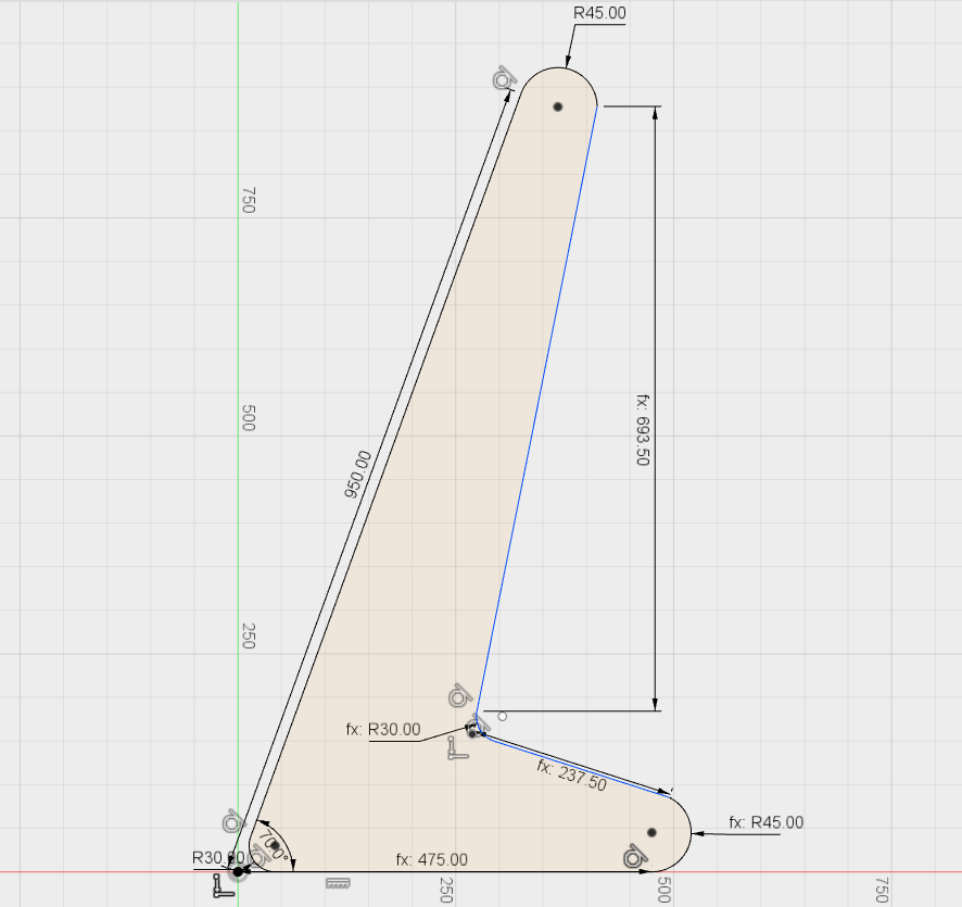
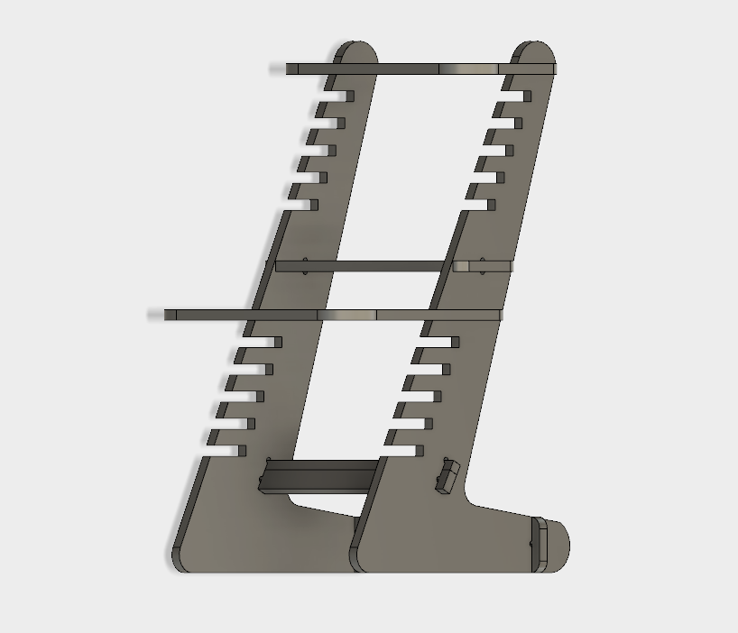
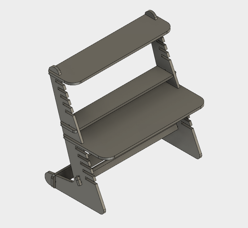
Final 3D Model.
As a result we obtain a nice looking standing desk which is scalable according to our parametric design capabiliy.
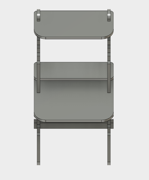
Here by changing the
Preparing the Files.
Before the job is launched, it is important to prepare the necessary files. For that, the .DXF files exported from Fusion 360 need to be imported into Rhino 5 software and rearranged into different layers.
The arrangement of layers has a couple of categories:
To achieve best results, one needs to first accomplish all the small/minor cuts with the smallest tool first on the inside. Then proceed with contouring/cutout of the big parts using the same or big tool instead. The rule of thumb is to go from insde to outside.
The resulting file, with different layers is then saved and imported into the machine.
Computer Cutting.
For the machine we used EasyWorker MasterPro 2513. The machine comes with a it's custom software which can load .DXF files and tronsform them into .GCODE.
Couple of important steps are required to troubleshoot the machine, these are choosing the origin point for X,Y,Z, turning on the Vacuumer, turn on the Ventilation and finally start the machine.
.jpg)
Here using the sensor the machine finds the Z axis of the bed. It is important to position the sensor on the actual bed and not the material. This is accomplished using the
.jpg)
This is the remote control using which we can directly control the machine. There is a side button on the right of the control, which needs to be pressed simultaneously with the buttons from the remote. Here are located the basic controls, same which can be found in software.
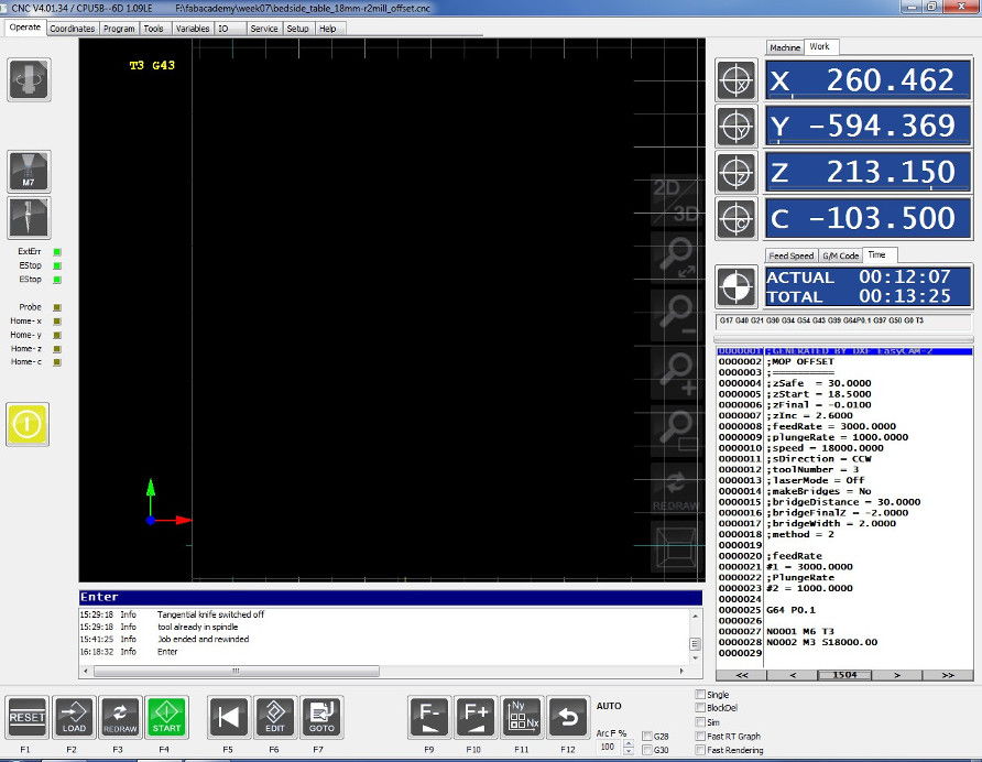
Software.
The software's interface presents with a vector model in the middle, which shows directly the job as it is, together with it's positioning. On the right hand side one can see the coordinates of the X, Y, Z axes as well as the gcode that is executed by the machine and the time which it takes to accomplish the job.
Here the user can control the machine as he would be able to do it with the remote control: changing the feed speed, start the job, reposition etc.
By going into the
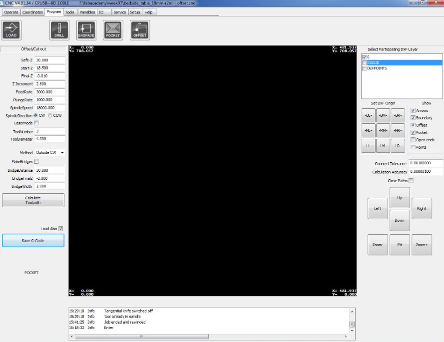
Cut Settings.
The settings used to cut the table for the
As a result we generate the gcode.
Before Launch.
Some crytical aspects to consider before launching the job:
To turn on the vacuumer, press the following buttons in fron of the CNC machine, according to the area.
.jpg)
Job in progress.
.jpg)
.jpg)
Final Assembly.
.jpg)
.jpg)
.jpg)
.jpg)
.jpg)