Embedded Networking and Communication.
Concept
The scope of this week is to demonstrate the networking capabilities, meaning any sort of communication/protocol that can be established between two boards. This week is intended to be used for the final project and part of the solution is incorporated within the Output Devices as the same board is used to produce some visual output, the goal for this week is to make the boards communicate between each other.
The communication interface for the networking week is infrared light. This is quite useful for nearby communication, which is intended for the final outcome of the final project, having nearby communication of small blocks, transmitting data protocols which allow different led lights to be triggered and form patterns.
A big advantage of the infrared is that it is not visible by human eye, being situated within a small proximity of the human eye visibility spectrum. As for the downside, it cannot pass through objects which allow low to no visibility.
Functionality.
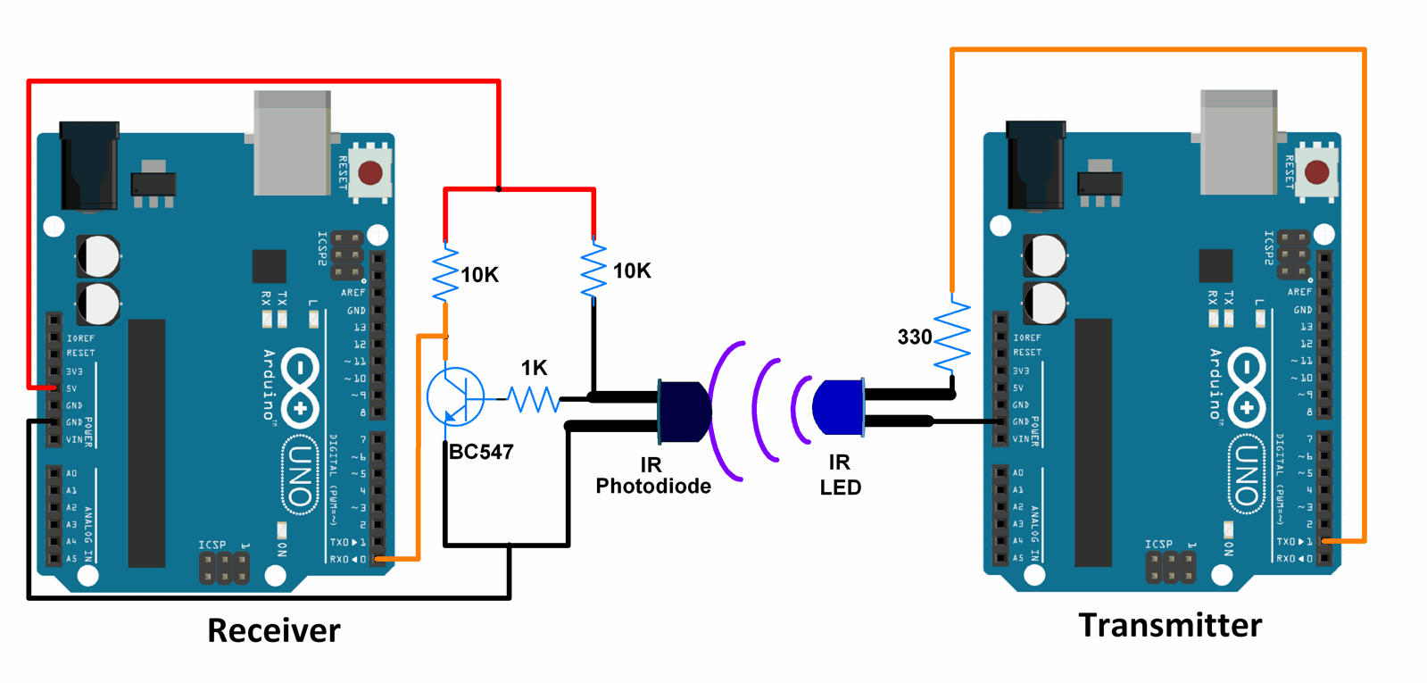
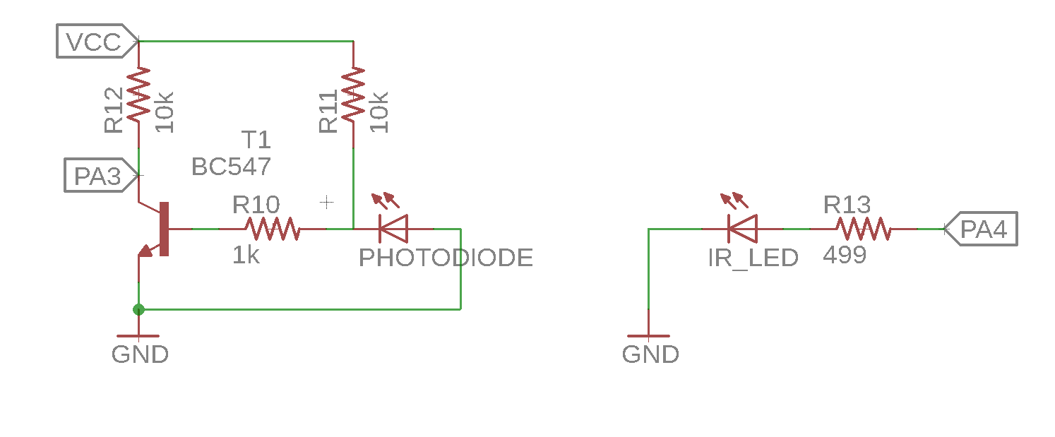
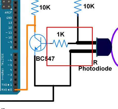
To allow the infrared communication, one needs an infrarred transmitter (IRT) and a photodiode transistor/receiver (IRR). For the IRT, IR204 is used, and as for the IRR PT204 is used. Both are quite cheap to get and have a 3mm mechanical built to allow embedding into small devices.
The IRT acts as a simple LED, it emits photons in the spectrum of infrared light. As for the IRT, it collects these same photons and acts as a trasnsistor instead.
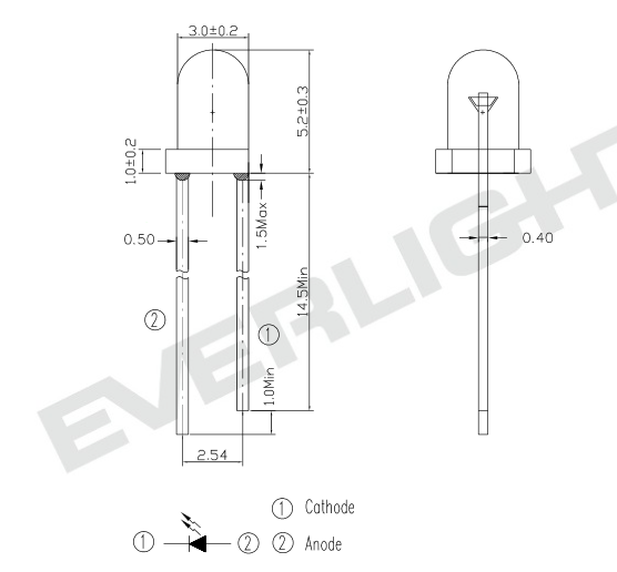
Infrared LED.
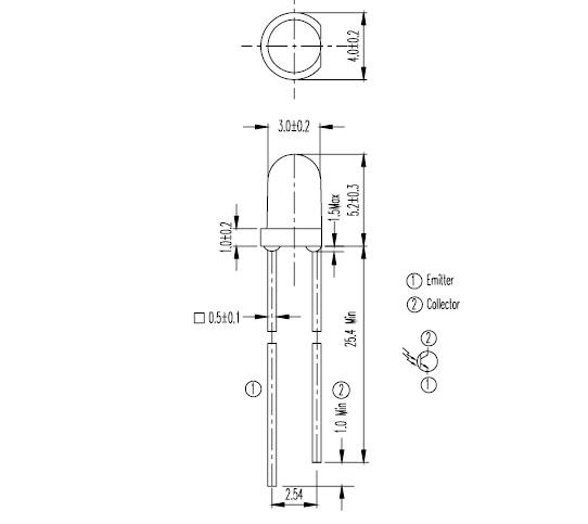
Photodiode Transistor.
In order to trigger the photodiode transistor another BJT transistor is necessary, since the amount of current is very low, the transistor helps to act as a gate switch triggering the pin.
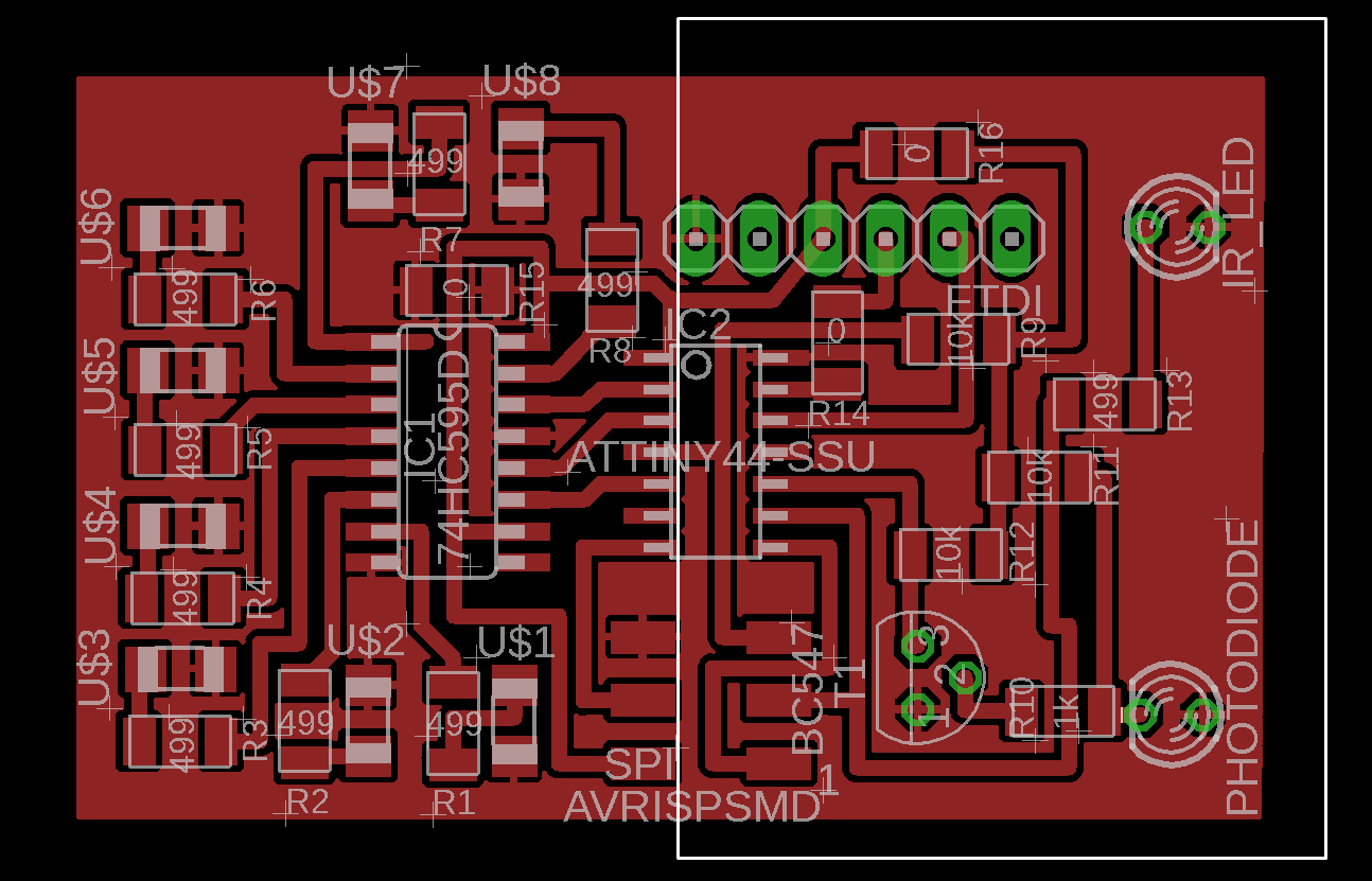
Boards Schematic.
The communication accross the boards is planned to be done using the main logic of the Output Devices week. This time the addition of the circuit is introduced: the addition of the IRT and IRR as well as the BJT transistor.
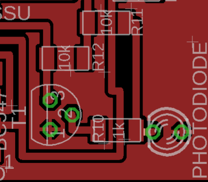
Boards Layout.
The part framed in white is relevant for this week's assignment and includes:
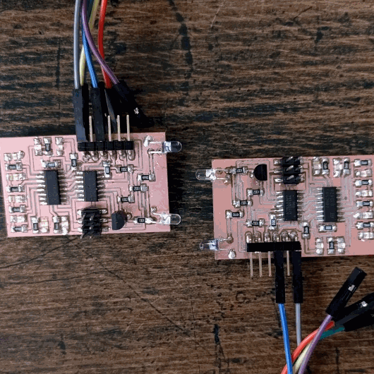
Production.
.jpg)
The production techniques are discussed in detail in the Output Devices week.
.jpg)
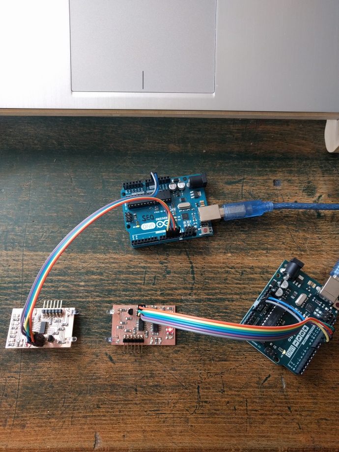
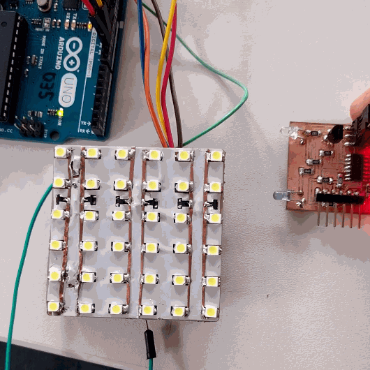
Two boards are reproduced to allow a comunication.
Programming.
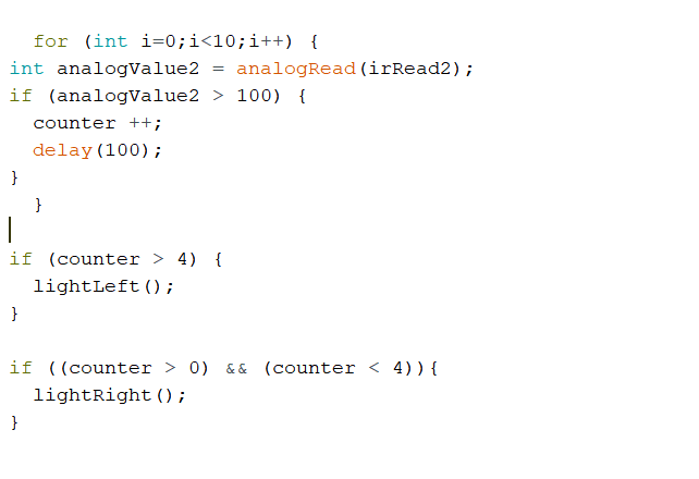
The idea behind the program was to enable the pin connected to the IR Led as digitalOutput and trigger it to be HIGH. As on the IRR side, enable the pin as analogRead input and play with the value to adjust the sensitivity.
The lights are triggered by the shift register introduced and most of the code for the output is taken from there.
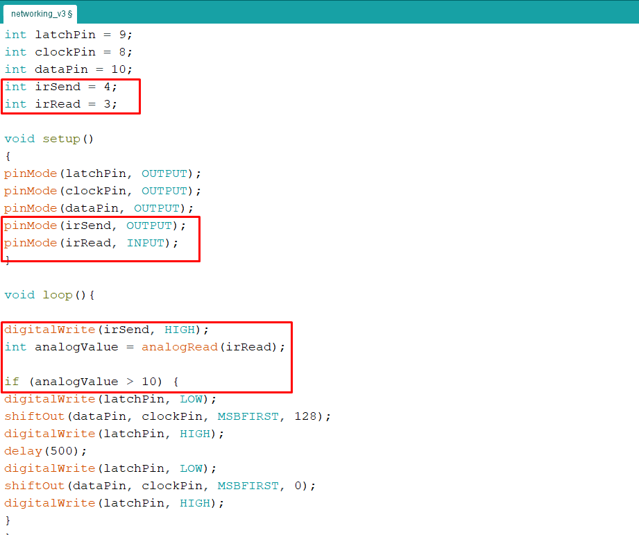
The new code introduces two new variables as analog input and digital output for the Attiny44 MCU. It sets the digital pin HIGH, meaning the LED is on full time and listens on the analog input channel to pick up any signal.
Troubleshooting.
After multiple attempts I couldn't manage to get the boards to be triggered. One assumption of mine was to change the resistance, but that didn't help.
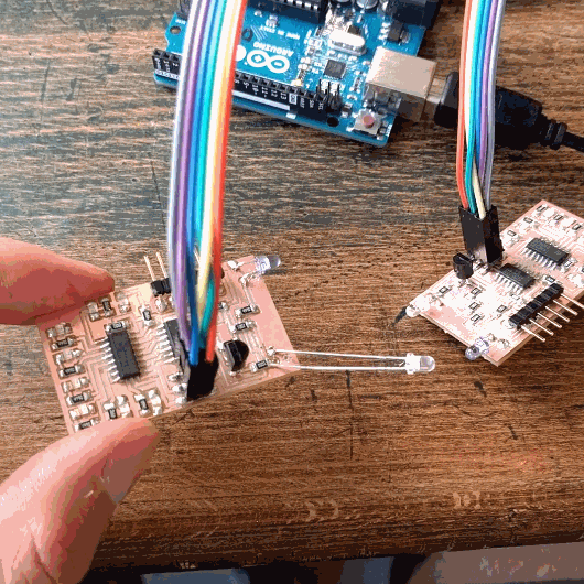
Looking back at the schematic, I realized that the IRR was positioned incorrectly. Instead of grounding the collector, I accidentally grounded the emitter.
This was a easy mistak to commit since the way I designed the board layout was counter intuitive to the actual setup.
Changing the orientation of the IRR fixed the problem.
The distance of picking the signal can be adjusted using the analogRead value.
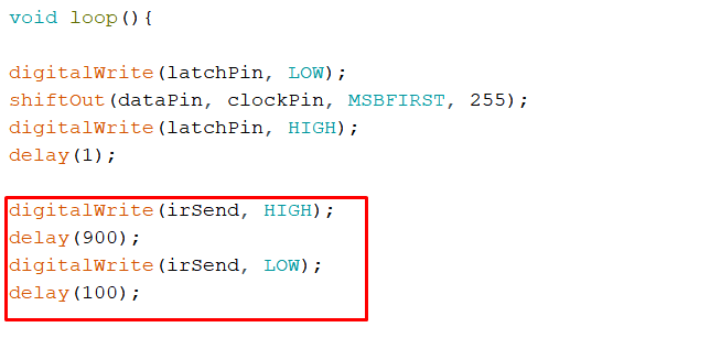
Addressing using Time Delay.
In order to test the recognition of different boards aka adressing, a time delay protocal is used using a counter unit.
Another Attiny84 microcontroller board, which is also the board of the final project, containing a IR reader,
On the other handside, the
As for the
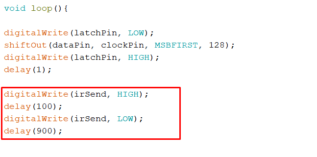
Testing the board shows how the Master is able to recognize between the two boards by using the time delay and counter protocol.
As a result playing with time delay and counter we can achieve different recognitions of the boards.