Machine Design.
Concept.
This is the continuation of the previous week's assignment of Mechanical Design. The overall documentation of the "BelissimoDraw" machine can be found on the following link.
The scope for this week is to automate the machine. As mentioned in the previous machine design week, the main functionality of the Y bed is having a stepper motor which controls a traveling belt. THis session will discuss the setup and operation of the motor as well as the finish up of the machine.
System Setup.
Since the intention is to build a drawing/plotting machine, the steps which are undertaken by the motors need to be precised.
A stepper motor uses steps as units of rotation. In order to correctly calculate the stepper motor size, which will later be introduced in the gcode software, couple of things need to be taken into account.
A Nema 17 motor is used to accomplish the movements. Having the datasheet of the motor, gives us an understanding of what kind of motor driver can be used.
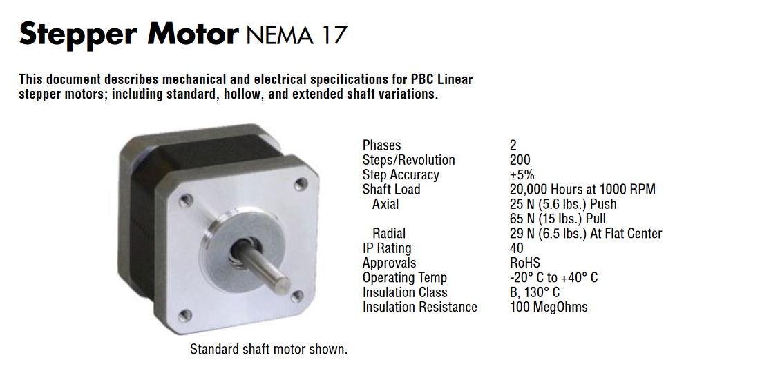
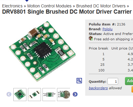
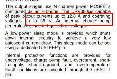
It mentions that the it can consume from 1.5A up to 2A current per rotation phase. This gives an impression of what kind of motor driver we can use. Gladly, in our inventory, the DRV8801DC Motor Driver is available.
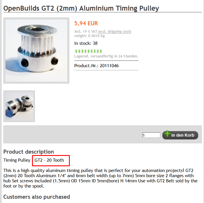
Another aspect is the pulley itself, knowing how many teeth the pulley has, gives a good understanding about the rotational torque.
Finally the logic board to drive the entire system is going to be Satshakit-GRBL intended with pinouts to allow controlling three axes by means of motor drivers.
Calculation of Steps.
Having all this information in mind, using an online tool provided here we can calculate the amount of steps per mm the system can take.
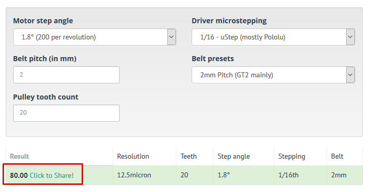
As a result, 80 steps takes the machine to travel 1mm. With these results one can achieve a high level of accuracy.
Gcode software.
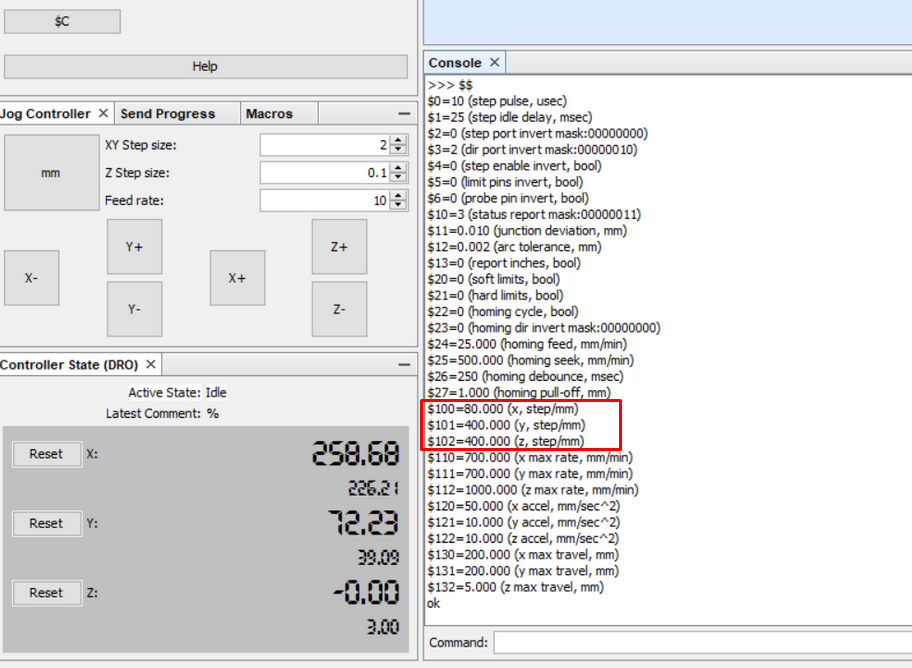
In order to control the motor(s), Universal G Code Sender Open Source software is used. It is designed to import and directly output the gcode, having a lot of user parameters for setup.
By typing in the
Cabling Work.
An important job nonetheless is to make the machine look neat and allow a free room of movement by setting up the cabling right.
Since the cables are the only conducting signal units and cannot be removed, putting them in order was the only solution.
The initial cabling of the machine was randomly placed.
.jpg)
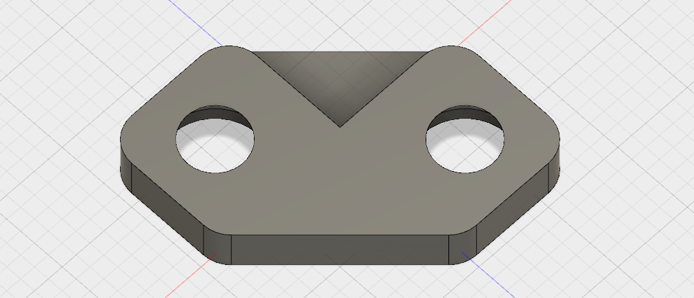
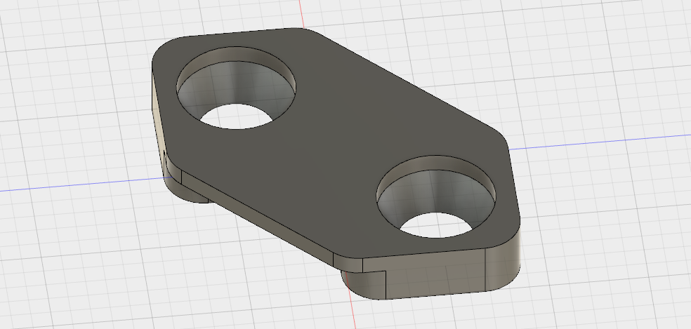
The solution behind was to print some small holders that could be fixated from both sides, by keeping the cable in the middle.
These small holders would also be holding the boards in place, since they didnt have any kind of fixation.
This was later printed in multiple copies to allow placing all the wires.
.jpg)
Slowly arranging the cables.
.jpg)
Satshakit-GRBL is getting fixture.
.jpg)
Same for motor drivers.
.jpg)
Cabling work is tricky.
.jpg)
.jpg)
.jpg)
The position was creatycal to allow flexibility of the movement.
.jpg)
Minimum cabling - best cabling work.
Finally, the cabling work looks much neater!
.jpg)
.jpg)