Computer Aided Design
Concept: Laser Cutter.
The requirement for this assignment was to learn to work with laser cutter as well as produce an object by using the technique of cutting, engraving as well as implement joints between parts.
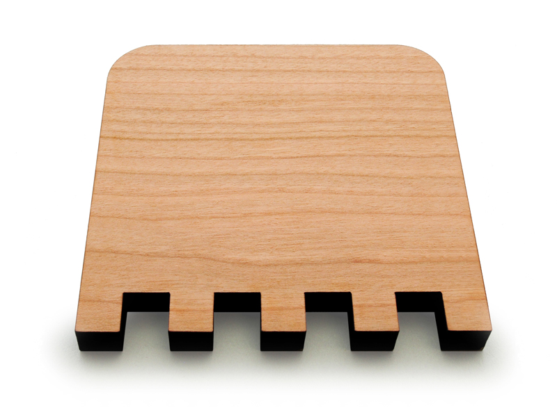
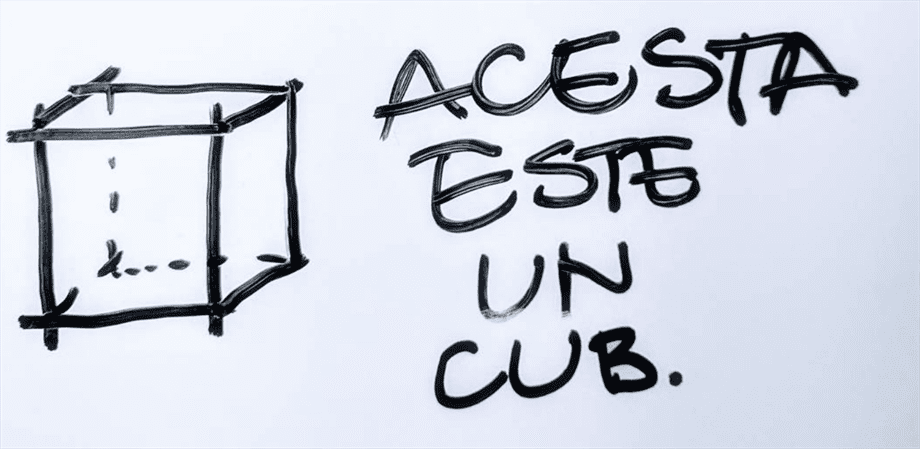
Initial idea was to build a regular dodecahedron (DOD) - a polyhedron with pentagon shaped faces, that would be displayed on the desktop as a nice accessory.
In contrast to cube, one of the most ubiquitous shapes, polyhedron takes a step further by extending the number of it's face to 12. With the goal in mind to learn better the
Since DOD has 12 sides available, it could easily be used for displaying some meaningful information or instructions. After a short brainstorm, the final concept evolved in producing an instructable of how to use the 30W Epilog laser cutter available in the Fablab HSRW. By using the dodecahedron as a case scenario, I intended to place the instructions on each side, along with examples of settings. Since I was anyways intending to learn how to operate the machine, it could be helpful to pass the information further.
The vision is to have the polyhedron attached to the laser cutter with magnets placed inside. Available at all times, anyone that would like to operate the machine, could simply grab the object, flip it around and follow the instructions. Once finished, the polyhedron is placed back to its place, on the laser cutter.
Parametric Sketch.
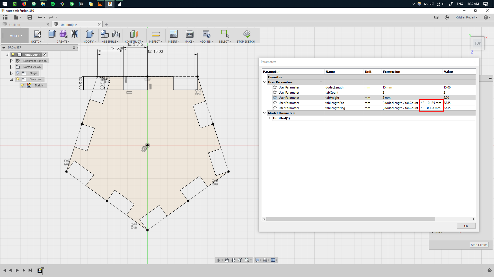
My intention with the model of DOD was to allow to ease the modification process, in case resizing was necessary or/and to allow anyone to replicate the object using his/her own dimensions. For that I decided to tap into
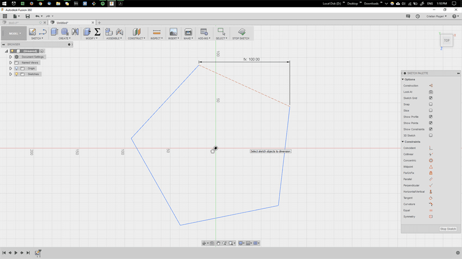
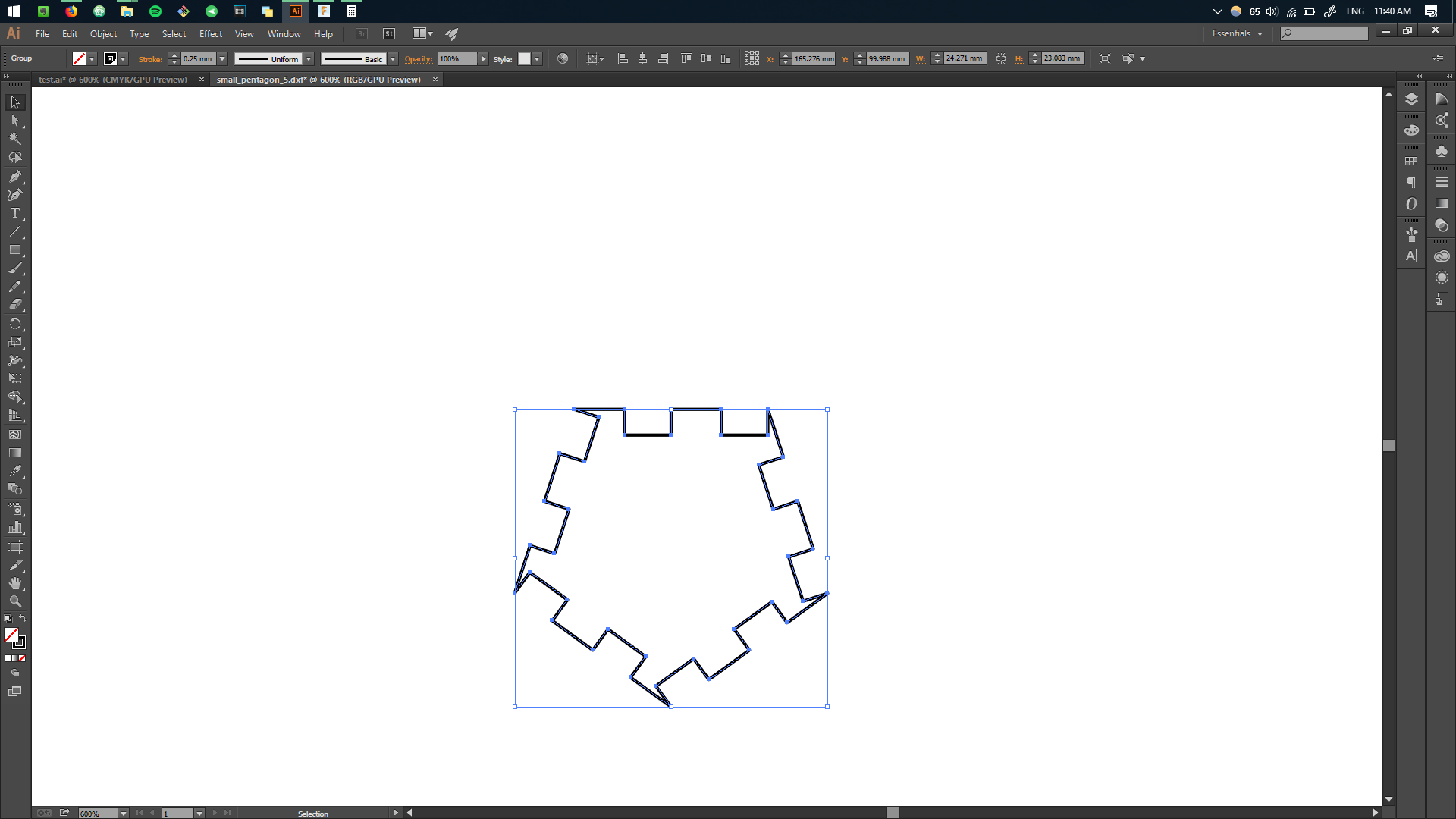
Breaking down the DOD to it's base shape, we arrive to the shape of the pentagon - 5 edges polygon.
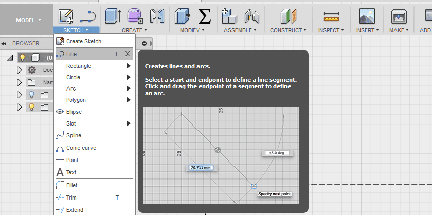
To create a polygon in fusion, we first enter into the
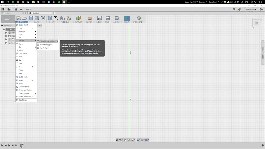
We draw a polygon by clicking using
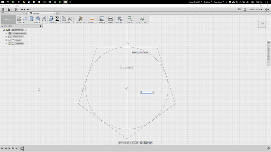
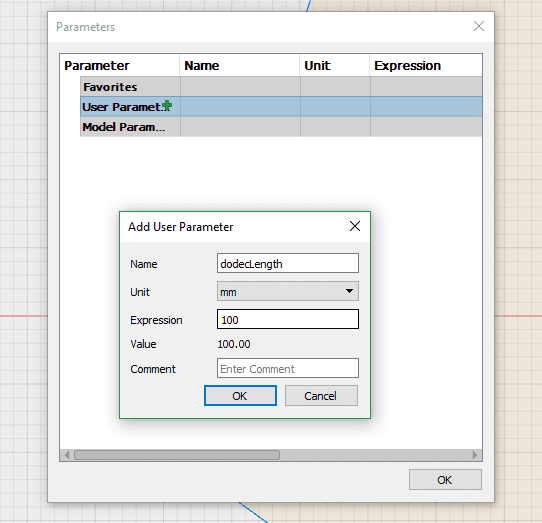
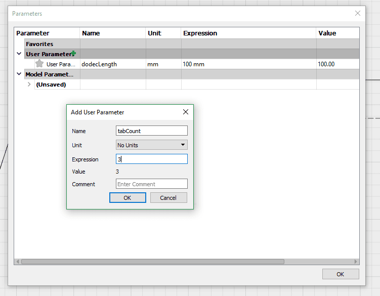
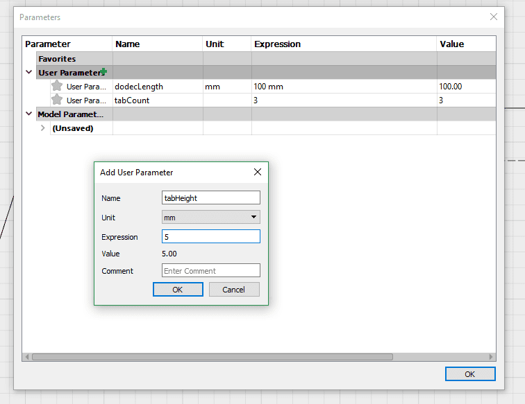
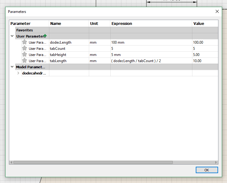
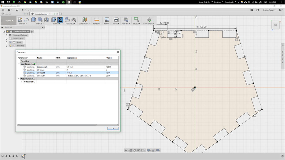
To enter our first parametric value, we go to 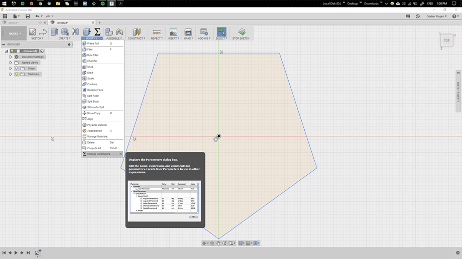
We would like to enter the value for the edge length of our DOD. We create a new
If we were to simply create a pentagon shaped face, we will lose the ability to connect each face to another. For this, we will want to use joint connections, which basically allows connecting side edges of each pentagon one to another, without using any external material, other that the absence of the material itself. The edges become more like lego blocks, while fitting one into another gives a mechanical grip and stability.
Having each face of the DOD connected to other 5 faces for each edge, limits us to which joints we could use. Also the laser cutter itself, cutting only in the X and Y directions, allows use to produce limited joint types. Considering also the fact that each edge of the DOD is connected to the other using an angle of 116.56 degrees, I decide to use the commonly used joint that looks like a square wave.
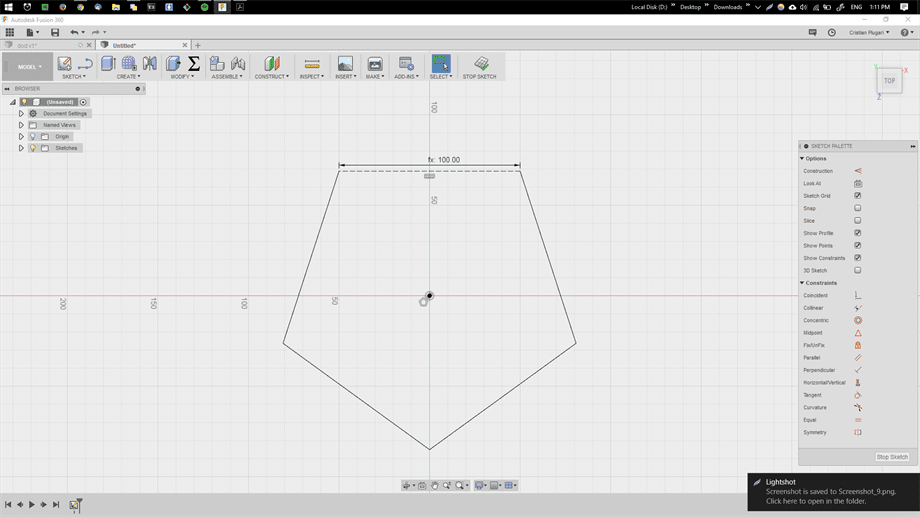
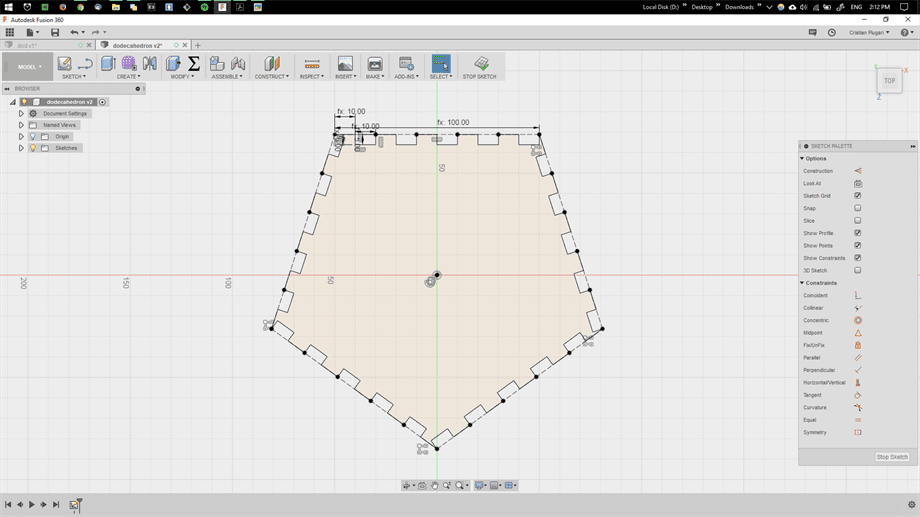
Sketch Constraints.
We won't be using the edge of the pentagon as an edge itself, however we will turn it into a guideline to see if by recreating the joints we are following the direction, length and angle of the pentagon's edge. For that we
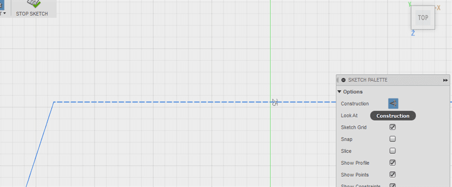
By
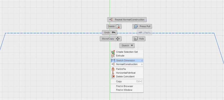
Instead of typing an integer digit for the dimension, we type in the name of the previous defined parameter, or
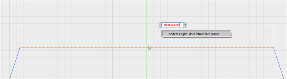
Once we do it, we observe the change of dimension of the edge to
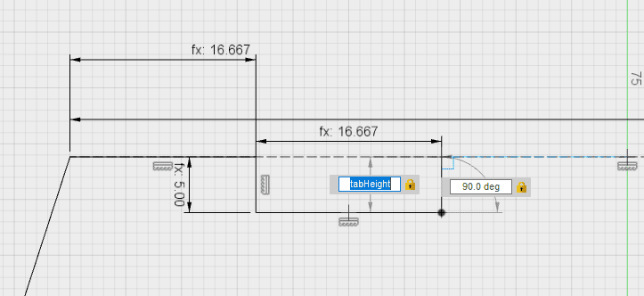
However we also notice that our shape has rotated. As we would like to keep the top edge parallel to the X axis, we go ahead and select our construction and in the 
This aligns our construction according to our contraint.
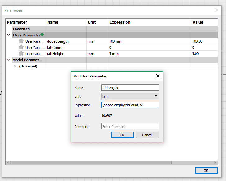
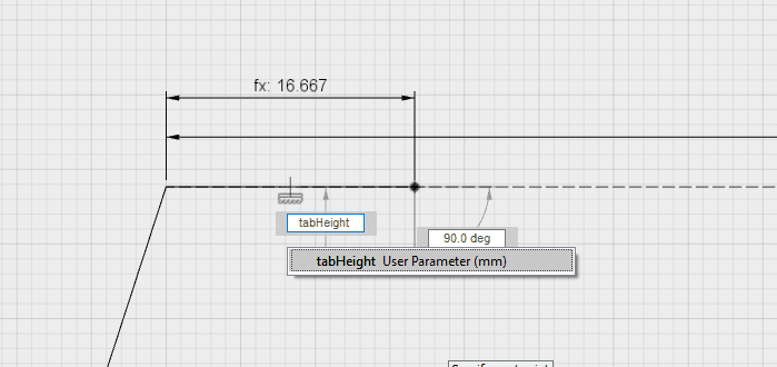
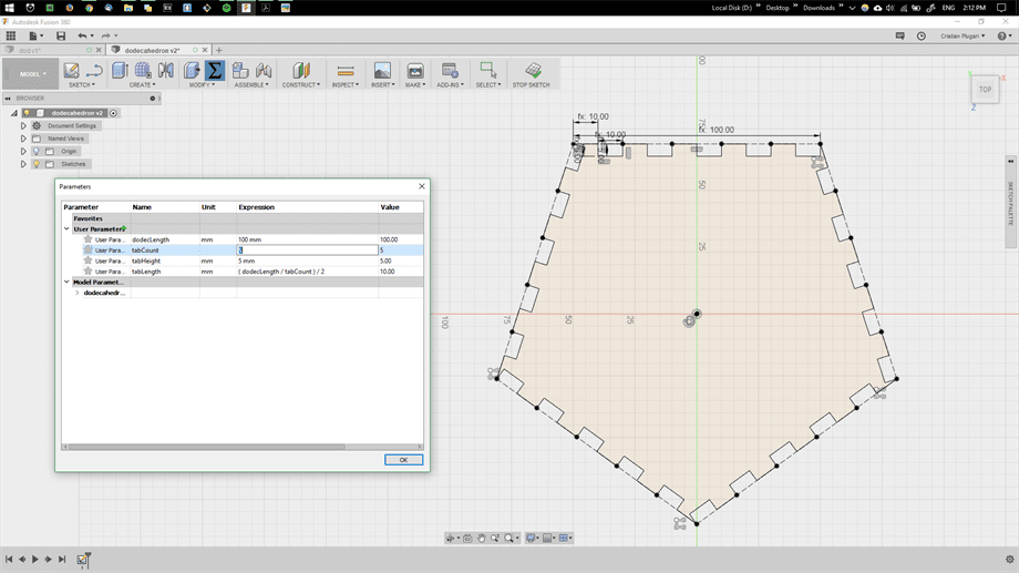
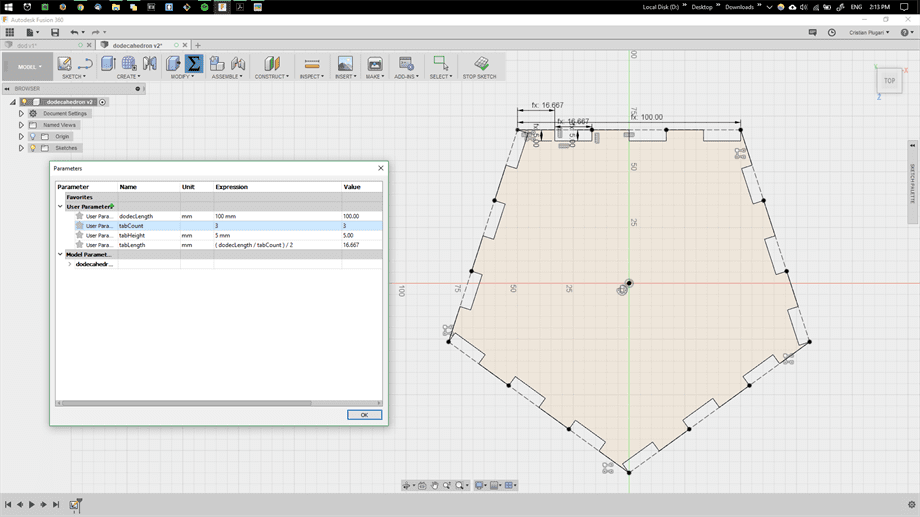
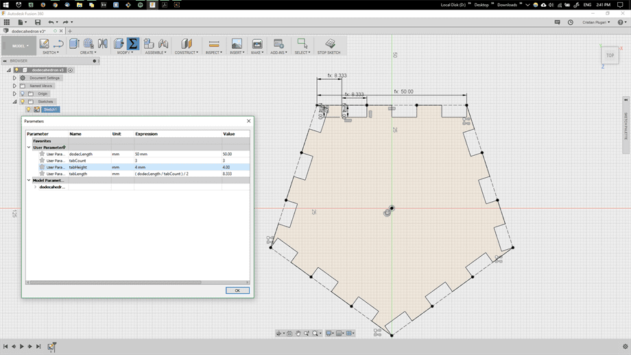
We would like to give some parameters for our tabs. A tab represents one of the tooth that together create the side joint of the edge. The length ,depth as well as the number of the tabs will influence how well the faces will hold one to another. Thus, we would like to define these parameters so we could later also modify them with ease. We access again the
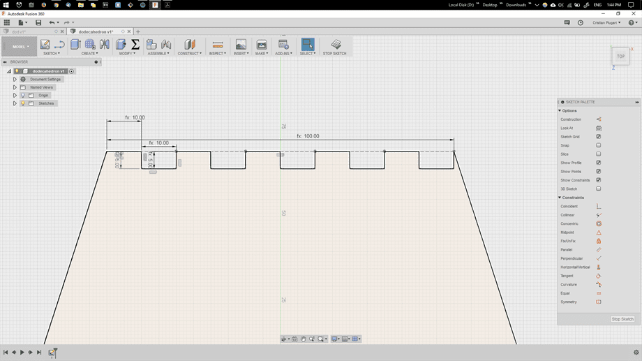
Now we go ahead and draw our side joint. In the
A line is drawn to our top edge/construction, of arbitrary length but with 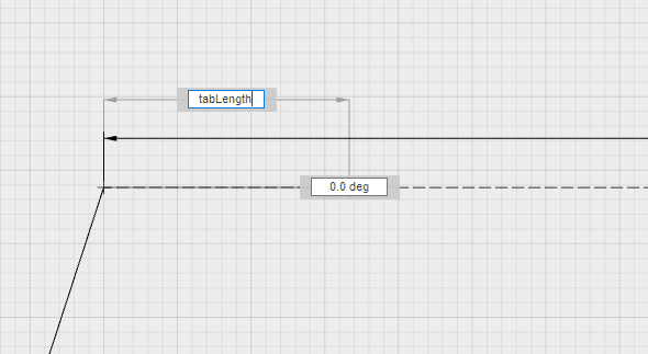
We draw a second line, coincident to the right extreme of the first line but perpendicular at the same time. Thus an
For the length of the negative tab, we use the same attributes as for the positive one
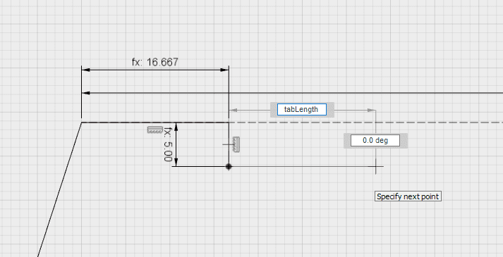
We also draw a line that completes the negative tab, again perpendicular to the edge and symmetrical to the second drawn line. For parameters we use
Patterns.
At this moment of time, we have created a nice square wave-like construction, which will serve as the base for our tabs. By having this square wave construction, we can use it as a base for creating a pattern that will continue along our edge. To create a pattern, we first go to
An
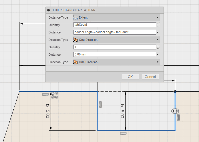
In the next example we see how the pattern is created by using a number of 5 tabs for the
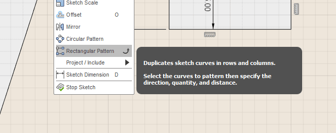
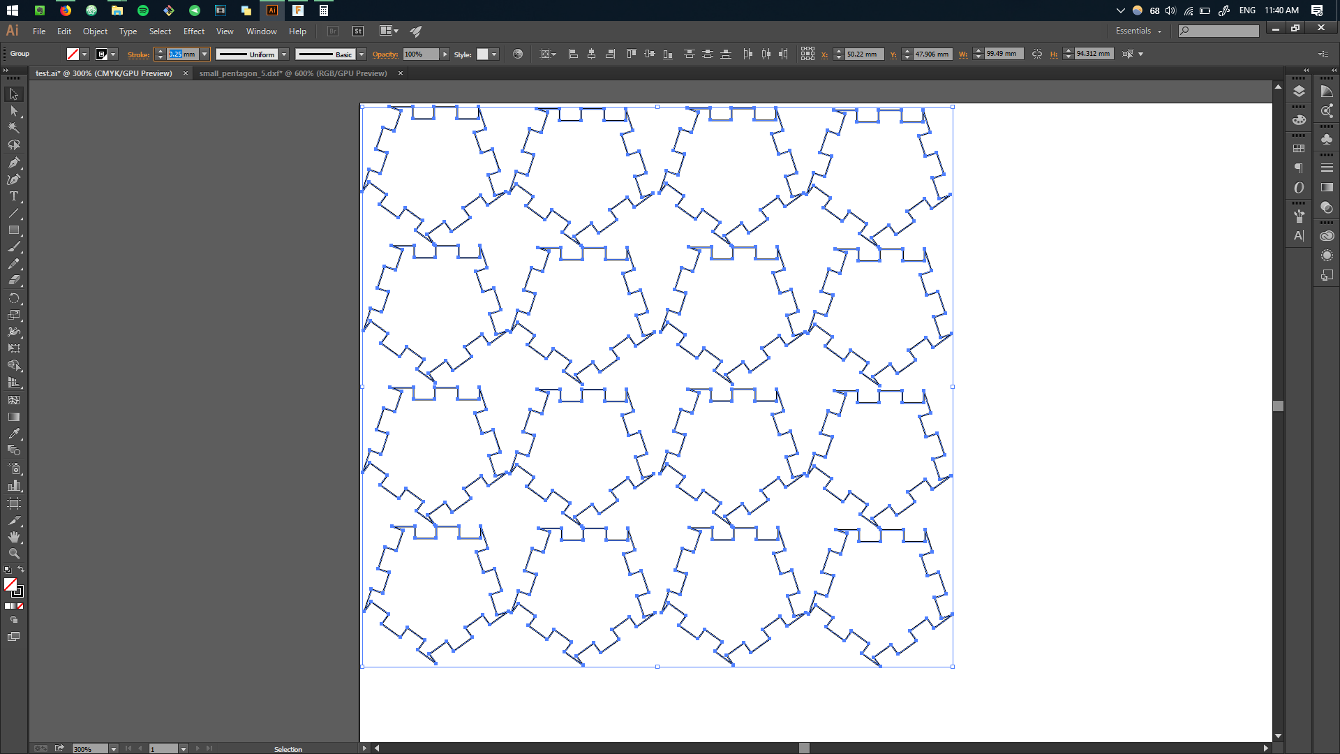
At this moment we successfully were able to create a pattern for one edge. We would however want to repeat the same operation for all other 4 edges. To accomplish that, the tool 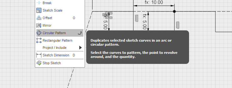
In a similar fashion we select our initial lines and as for the
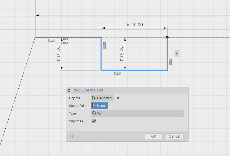
To space the objects according to each edge, we enter
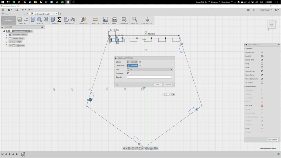
Before proceeding, we make sure to attribute to each newly created pattern at each edge, the same parametric values as we did for the first sketched lines. Because the newly created patterns do not hold metadata about the original pattern they originate from, so specifying
We continue by again using
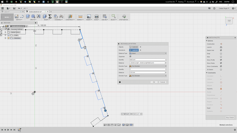
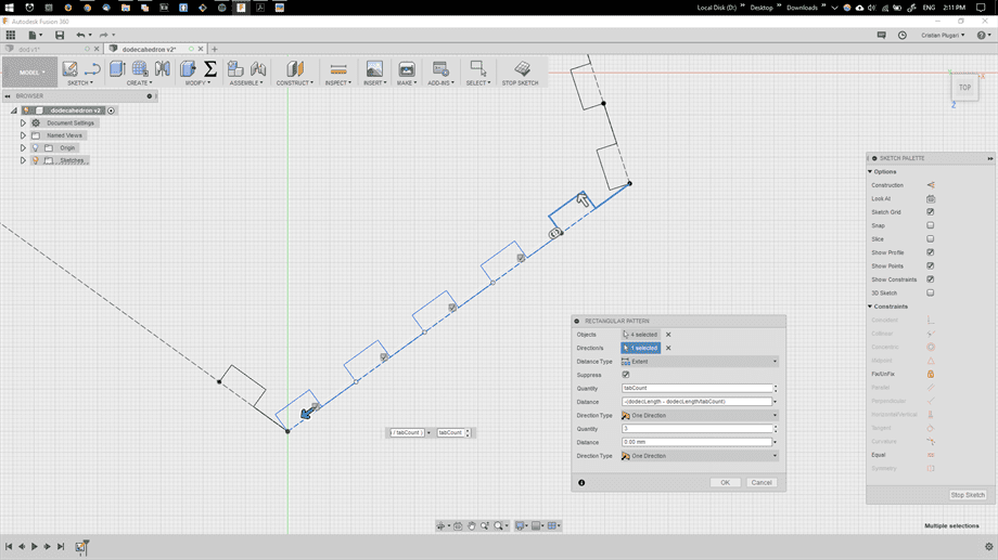
As a result, we created a pentagon shape with tabs for each edge, that is parametrically adjustable according to our need, material etc.
To test the responsiveness of our coded shaped, we can go to
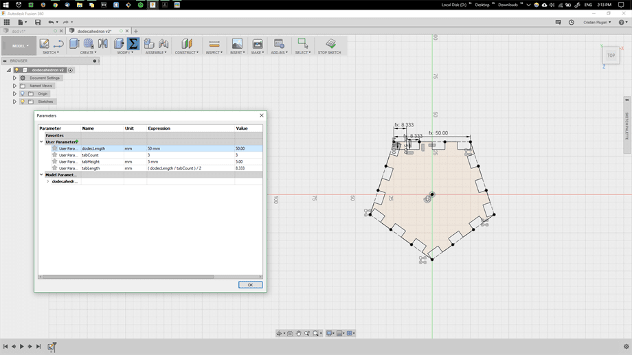
Now we can easily create our own desired dimensions to fit any design. That's the beauty of parametric values.
Testing the Laser Cutter.
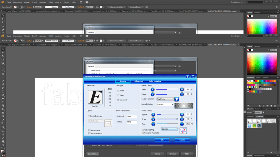
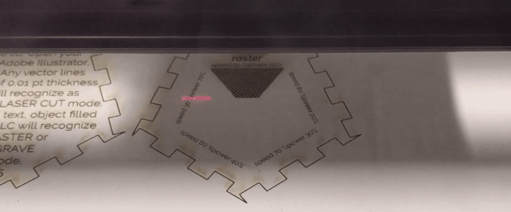
Having my shape ready for laser cut(LC), I decided to experiment at first to understand the behaviour pf the LC and the change of it's printing parameters.
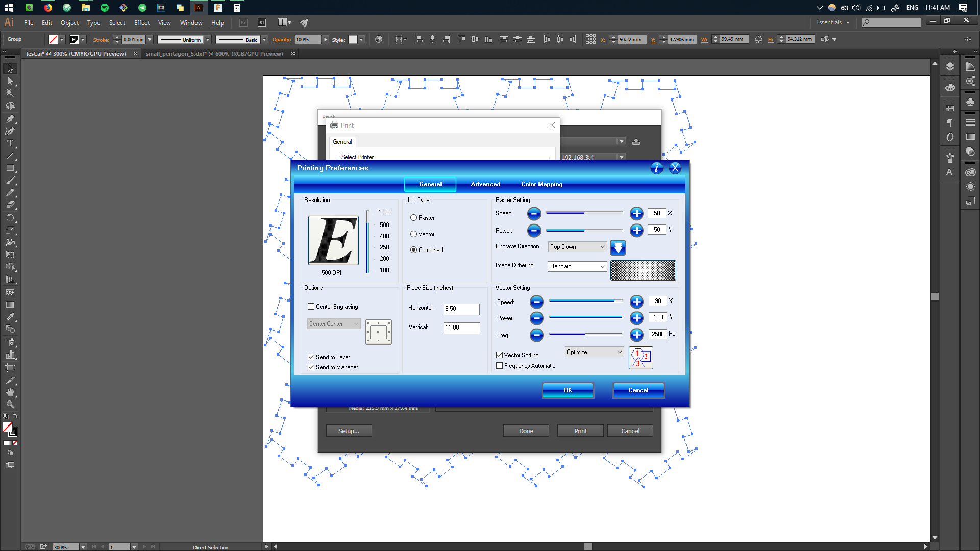
For this specific project, I focused my efforts on learning the
.jpg)
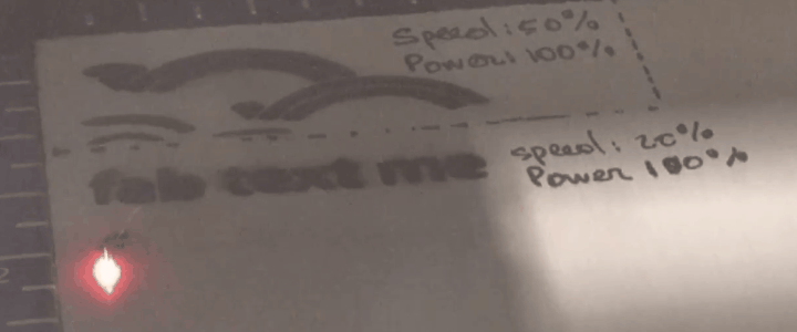
I made sure to note the settings I used for each operation, to get a perspective of how each setting affects the process.By experimenting with different patterns and text writing, I could clearly get an idea how the
.jpg)
.jpg)
In order to better understand how the
.jpg)
As a result I learned that LC operate in two different modes. Either
In order to operate in the
I finally arrived to the conclusion, that the most efficient way to cut out a shape using the
.jpg)
The cuts were done without burning too much of the material, however I encountered a problem while assembling the pieces. The faces were not
.jpg)
.jpg)
Experimenting with Joints.
Joints between the faces were loose. In order to avoid gluing them together, we would have to modify either the length of the positive tab or the length of the negative tab.
Before committing to any modification in the design, I decided to print out 12 faces, to see for myself whether assembling the entire polyhedron would give a mechanical stability. I used
.jpg)
.jpg)
.jpg)
.jpg)
However I quickly realized that the stability will not exist without using a tape. Thereafter I removed the tap once it was fully assembled, to see how it looks in entirety, however the mechanical stability was yet not there.
.jpg)
.jpg)
However by holding the object in hands and passing it to colleagues, It was obvious the construction is not rigid and will not last for too long.
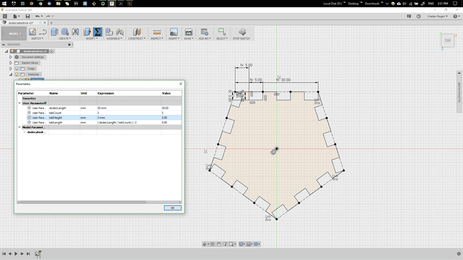
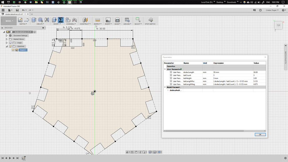
Adjusting the Kurf.
To improve the stability of the DOD, I experimented with reducing the joint's sizes. I decided to change the length of the negative tab. For that I had to firstly separate the two distinctive lengths of the tabs one for positive and one for negative. I then proceeded by adding
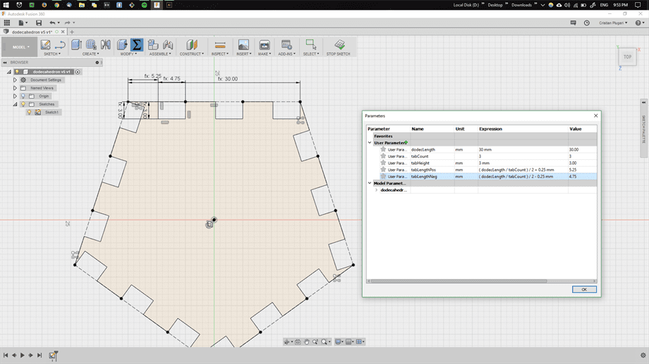
Then I printed two copies of each edge to test joint's press-fitness.
.jpg)
I then proceeded by printing a couple of
.jpg)
As the writing states, I concluded that this change of parameters, with
As a result, I concluded that this provided a good hold of the faces as well as added some flexibility, which allows the faces to fit one into another.
.jpg)
.jpg)
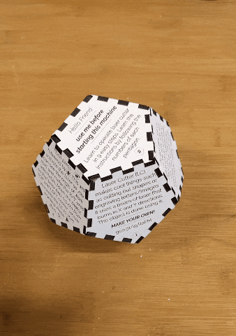
At this moment I have successfully established the vector and raster settings for the laser cutter, created a parammetrical shape which is resizable, found the right approach for the joints. It was time to pick my size, choose the right material, design each face as an instruction for the
Final Prototype.
For the material, I chose the 3mm white coated MDF(medium-density fibreboard) left as a spare material from the "Green FabLab" project. This material comes from the same family as plywood, so I expected to get similar results when working with the laser cutter. I chose particularly this material because I wanted to give the object a nice white color as well as more rigidity and a fine look. For the dimensions, I experimented by cutting out
.jpg)
.jpg)
I realized that I needed a size in between to enlarge the object's surface for the text that will be printed on top, as well as not to over exceed it in size, in order to keep it comfortable when holding in hands. Ultimately my design characteristic shifted the dimensions to
To test how many words would fit into one pentagon, I chose a font size of
.jpg)
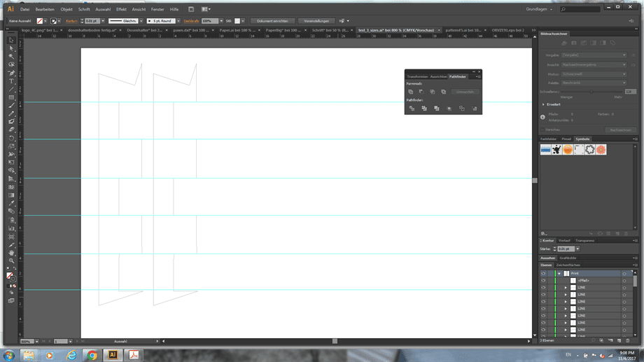
Some experiments on the white MDF gave me an idea of how the material behaves once exposed to the laser. To facilitate the printing process and create a neat look, I broke down the layers in Adobe Illustrator into 6 different layers. Each layer is either using the
.jpg)
I wrote the instruction for the printer which I thought would be suitable, short and simple to comprehend.
My design is ready, final printing was left.
.jpg)
.jpg)
.jpg)
.jpg)
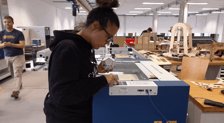
Once printing was finished, assembling the components together was a easy job. For the face that is the bottom side, I intended to to use glue to stick magnets. This would allow a better grip to the metallic shell of the LC.
.jpg)
.jpg)
.jpg)
.jpg)
.jpg)
.jpg)
Besides the link that is placed on the surface of the DOD, which leads to this tutorial page, I also made sure to include an
.jpg)
.jpg)
.jpg)
.jpg)
.jpg)
.jpg)
.jpg)
.jpg)
.jpg)
Voila! Ready for user test!
.jpg)
Assembling in Different Ways.
To push it even further, I tried to reproduce one face on a smaller scale and assemble it in different ways. For that, first scaling was required.
I adjusted the size and kurf using the parametric design.
As a result I get the DXF which I replicate to have more building blocks.
The settings used for cutting using the laser are the following: SPEED:90% and POWER:100%.
.jpg)
Using the cut pieces, it is possible to assemble different shapes and achieve some variation in building.
.jpg)
.jpg)
.jpg)
.jpg)
Download Files:
Concept: Vinyl Cutter.
For the vinyl cutter assignment I decided to vectorize an image retrieved from social media, after which to cut it on the stencil sheet in order to obtain a sticker.
The stencil sheet is made out of a layoer of the sticky vinyl and a the protection layer underneath. The goal is to cut out the vector on the sticky part, by leaving the protection layer untouched.
1. Preparing the Vector.
To accomplish the job, we will be operating the Silhouette Portrait 2 machine. The software can be downloaded here in order to get the environment running.
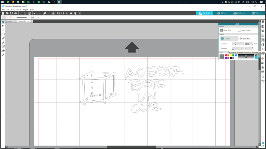
For the concept of the final sticker, I picked on of the images from my social media accounts. First we will download it as it is.
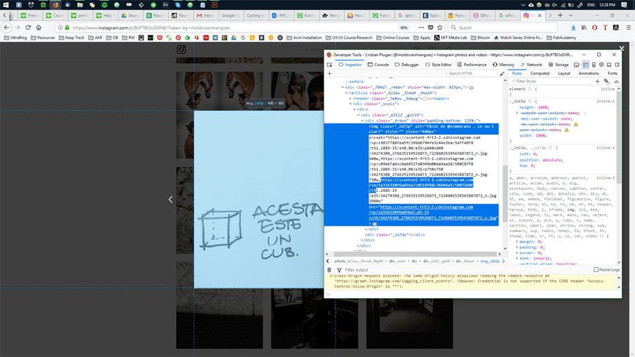
In order to vectorize the image, I am using Adobe Illustrator. After importing the image and choosing
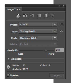
These settings may vary according to the desired look and amoun of detail one wants to achieve. In my case I got the followings:
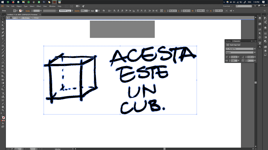
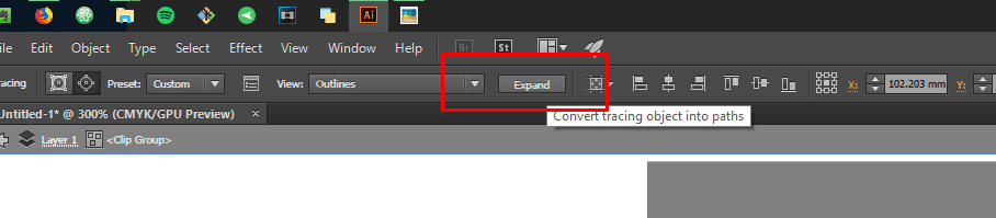
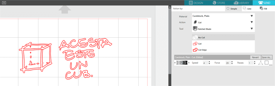
As a final step, in order to transform the current trace into vector lines, we go ahead and select the target object and click on
And voila, before, the original image and after, the vectorized image:
2. Working with Silhouette Printer.
I tried to find a good color that would match the back of my laptop, as the final target for sticking my sticker. The choice between black and red, ended up quite easy - red.
.jpg)
Knowing the size of the sticker we want to cut, a block of material is cut and positioned on the top-right corner of the sticky pad that is provided together with the printer.
.jpg)
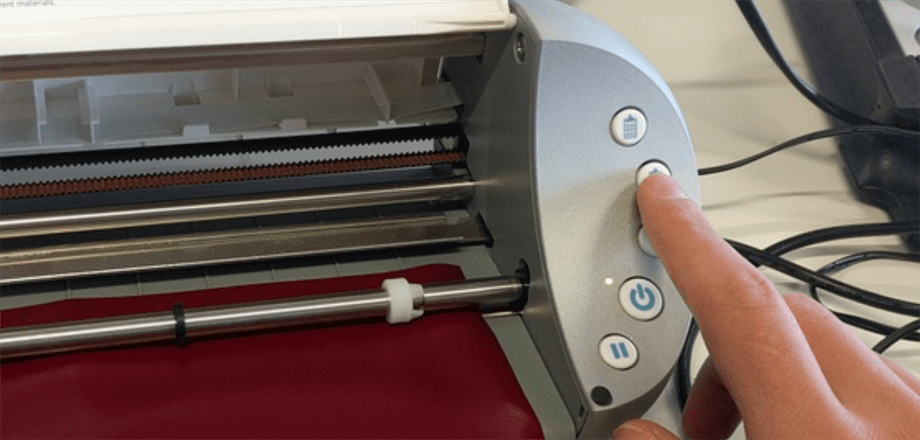
In order to fixate the material inside the printer, the second button from the top is pressed and the material is slowly introduced to it's origin point.
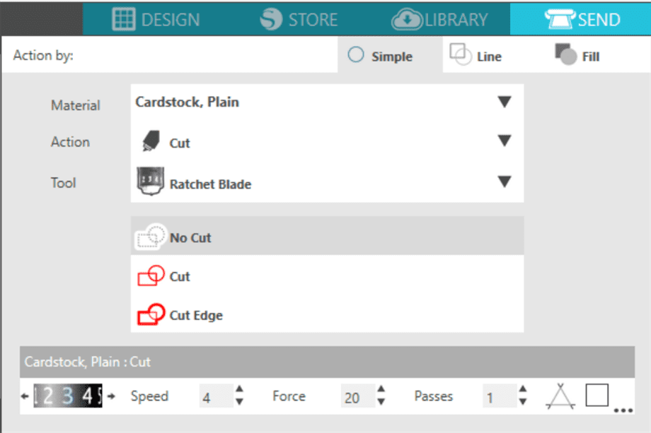
3. Operating the Software.
Once the Silhouette Software is initialized, we can choose the printer as well as the settings we want to cut with. As a testing print, a tag shape was chosen. Also
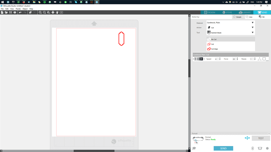
Here are the crytical settings chosen to print the first shape.
As a result, our cut was too deep, and the protective layer was cut as well.
.jpg)
4. Changing the Blade.
To decrease the depth of the cut, the inside knife tool is removed and set from the value of 3 to 2, by rotating the knob clockwise.
.jpg)
Now we are ready to load our file, and to produce the final sticker.
The vector image is dragged and dropped inside the software, after which it is repositioned to match our material positioning.
Before sending the job to print, the settings of the blade are changed accordingly to match the number of the knife tool, which is 2.
We position the material accordingly.
.jpg)
5. Last Steps.
The vinyl is printed and the result is satisfying.
.jpg)
Last steps involve removing the excess material around the cut and inside, that we do not want to show on the final sticker.
.jpg)
.jpg)
In order to transfer the sticker from the protective layer to the final object, we use a layer of paper tape which is sticker on top of the sticker. This would grab the sticker and easily transfer it on the desired object.
.jpg)
.jpg)
Now we can trasnfer the sticker on the desired location, back lid of the laptop.
.jpg)
.jpg)