Embedded Programming.
Concept
For this session we had to write a code using C langauge. Having Arduino IDE that displays the higher language of the code, C code communicates directly to the micrcontroller by writing the data into the registers.
Arduino Code.
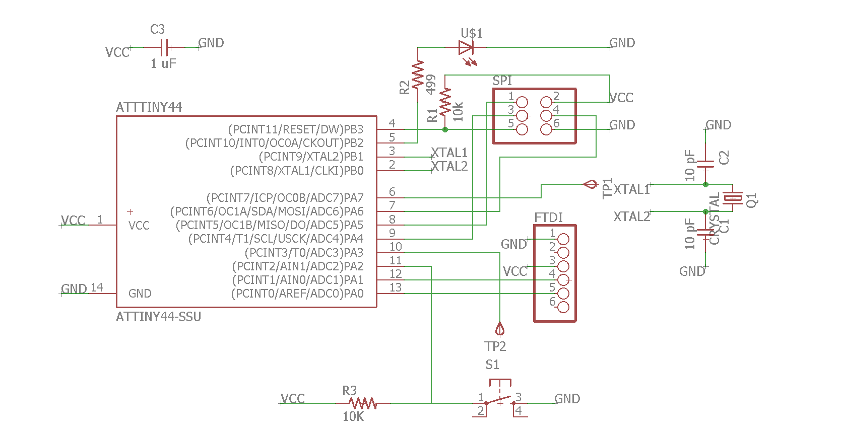
Having previously done the Hello World board, it will be used as the board on which the program will be written. This board has one input - button and one output - led.
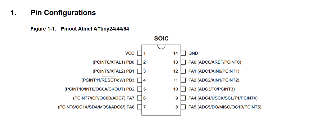
Here the Attiny44 MCU is used.
The simple program is to make the LED blink according to the press of the button.
In the following code the pins of the Hello World board are used ht at correspond to the schematic of the board:
                        const int buttonPin = 11;
                        const int ledPin =  5;
                          int buttonState = 0;

                        void setup() {
                          pinMode(ledPin, OUTPUT);
                          pinMode(buttonPin, INPUT);
                        }

                        void loop() {

                          buttonState = digitalRead(buttonPin);

                          if (buttonState == HIGH) {
                            digitalWrite(ledPin, HIGH);
                          } else {
                            digitalWrite(ledPin, LOW);
                          }
                        }
C Code.
Here is the translated code into C.
                    #include <avr/io.h>
                    void main(void) {
                    DDRD &= ~(1<<DDA2);  // PA2 as Input
                    DDRD &= ~(1<<DDB2);  // PB2 as Input

                    PORTD |= (1<<PA2);  // Pullup PA2

                    while(1)  {

                    if((~PINA & (1<<PA2)); // Button pressed
                    PORTB |= (1<<PB1);   // LED is on
                    else
                    PORTB &= ~(1<<PB1); // Else LED is off  } }
Explanation of Code.
DDRD &= ~(1<<DDA2); // PA2 as Input
This sets the PA2 pin data direction to input. Similarly to PB2 that follows.
PORTD |= (1<<PA2);
This enabled the internal pullup resistor of the MCU, to be later triggered when the button is shorted to LOW or GND
while(1) {}
This creates an infinite loop, as long as 1 is true.
if((~PINA & (1<<PA2))
This states the condition if the PINA bit-level is shifted to HIGH state.
PORTB |= (1<<PB1);
Create a bitwise OR function between PB2 and PB1, as a result the LED is on.
PORTB &= ~(1<<PB1);
In contrast, create a bitwise AND function, as a result the LED is off.
Upload to Board.
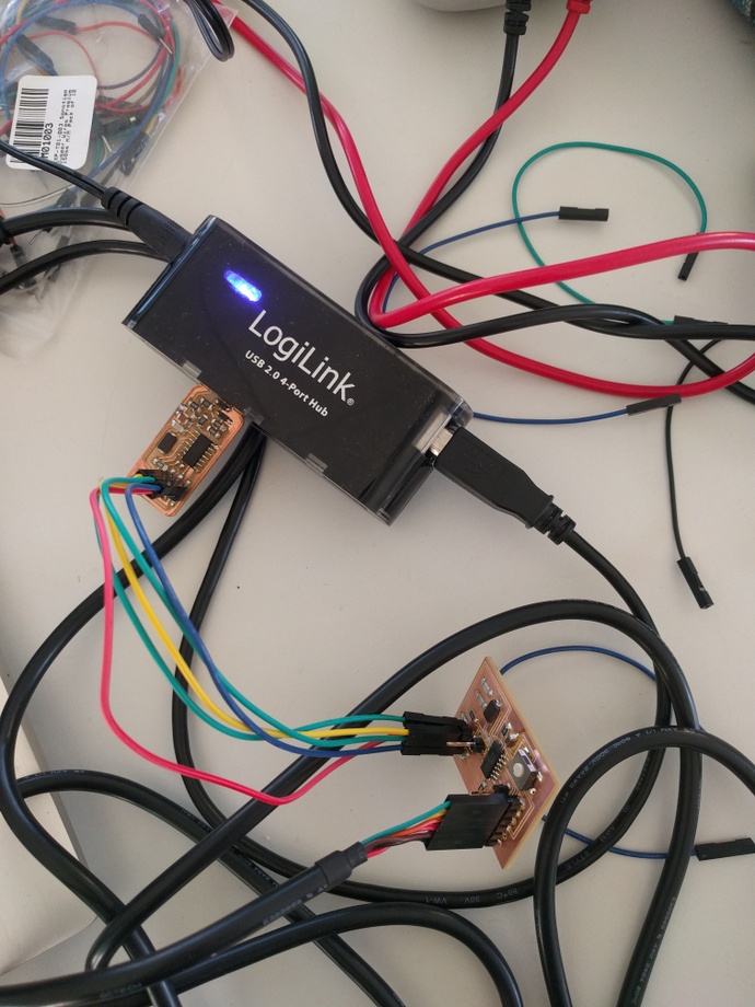
To give life to our board, it is crytical to install the bootloader. Here the FabISP board will be used, previously created in Electronics Production week. We connect the FabISP to our Hello Board by means of SPI, avoiding the 5V connection. For that the FTDI cable will come in handy, which is connected to the other UART interface.
To "burn the fuses" or bootload the board, one needs to download the firmware.zip and extract it somewhere in the PC.
To accomplish the programming one can follow either the tutorial here or the description below.
This is the Makefile code by means of which the blinkLed.c code will be deployed onto our MCU board.
                        PROJECT=blinkLed
                        SOURCES=$(PROJECT).c
                        MMCU=attiny44
                        MCU=t44
                        F_CPU = 20000000
                        CFLAGS=-mmcu=$(MMCU) -Wall -Os -DF_CPU=$(F_CPU)

                        program-usbtiny: $(PROJECT).hex
                             avrdude -p $(MCU) -P usb -c usbtiny -U  flash:w:$(PROJECT).c.hex
                        program-usbtiny-fuses: $(PROJECT).hex
                             avrdude -p $(MCU) -P usb -c usbtiny -U lfuse:w:0x5E:m
This Makefile is adjusted to the previously created Hello Board. Changes to MCU type as well as the clock can be defined in the header.
Having this Makefile as well as our blinkLed.c code, we can go ahead and burn the fuses onto our board. Similar to the Electronics Design week.
make -f makefile.make
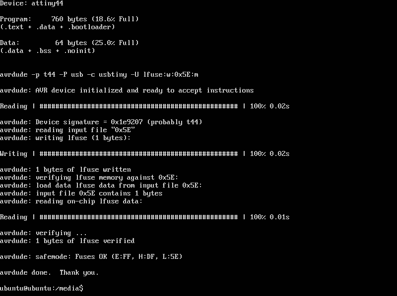
Here we are burning the fuses to the board.
make -f makefile.make program-usbtiny-fuses
Finally we write the new program into our board.
make -f makefile.make program-usbtiny