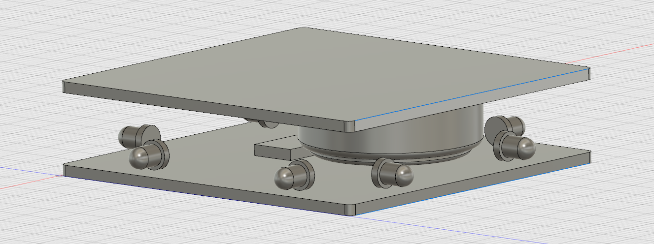
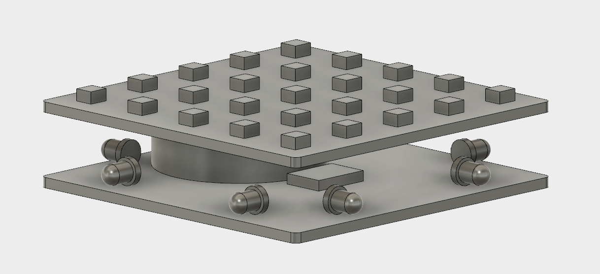
Model of the system.
Concept.
The idea is to create a model that represents the physical built of the final project. This would allow a better understanding of the physical limitations of the system and easily manipulate changes in 3D. This implies modeling the entire object in 3D, parts of which will be extracted for 2D use later on in the process. Having this in mind, I decided to work towards my final project and as a tool, use the ubiquitous tool provided by Autodesk, Fusion 360.
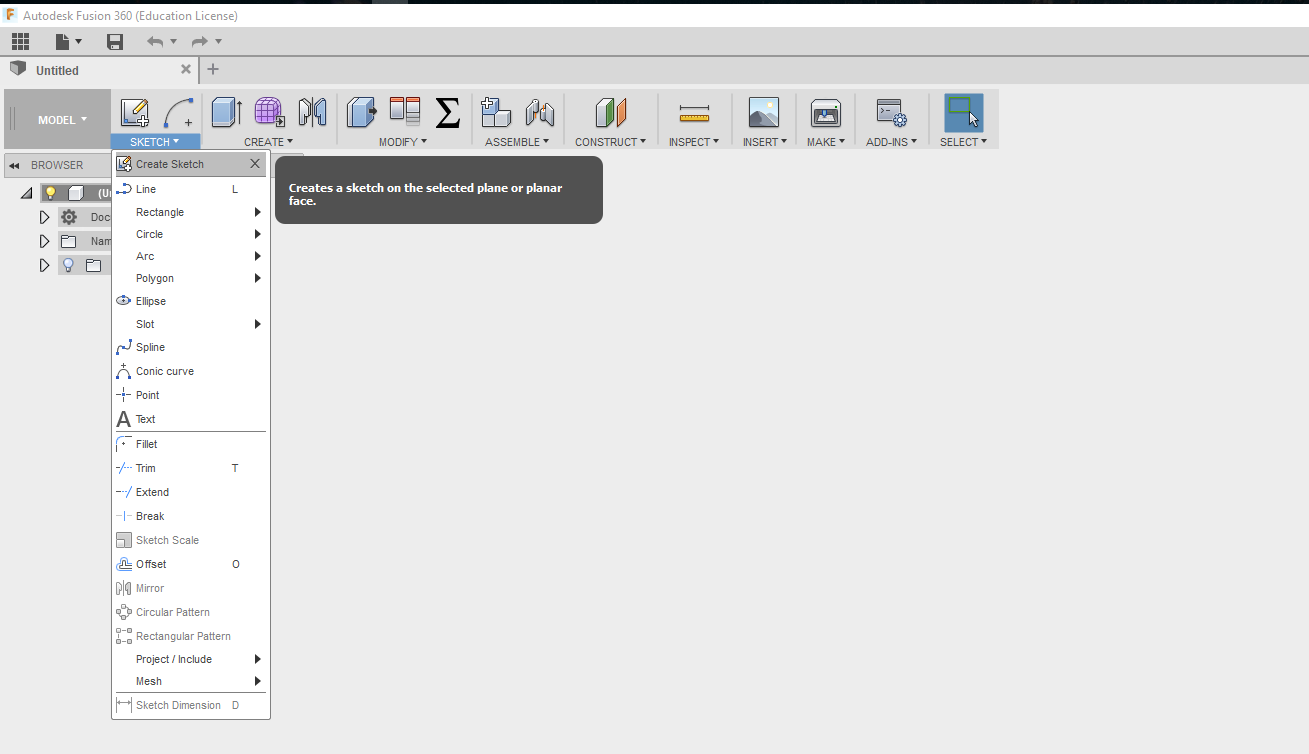
2D Design.
Fusion comes handy in creating 2D designs which the software defines as sketches. The name "sketch" is quite intuitive, as one creates a 2D digital sketch, with all the necessary measurements and parameters he/she can later on rely in order to "extrude" the 3D objects. The sketch is easily accomplished in the "Sketch" tab, by selecting the necessary tool to work with.
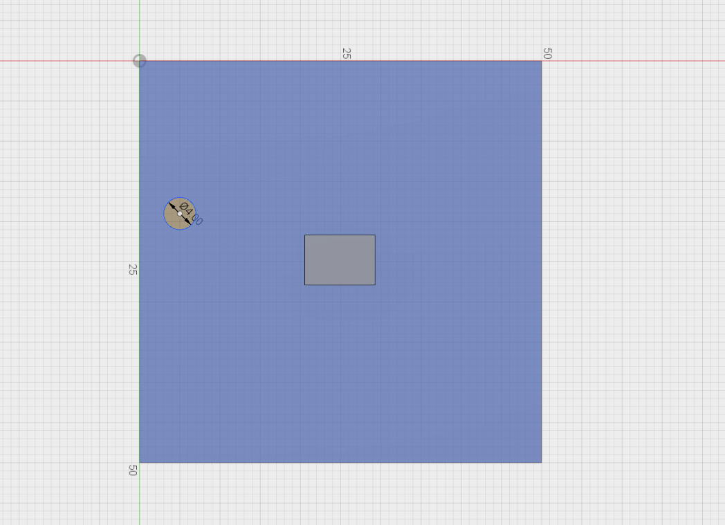
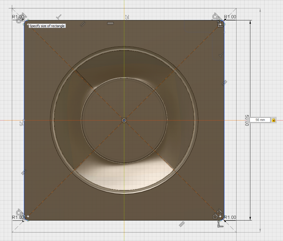
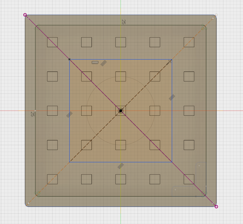
Since the concept of the final project is to have a modular cube, we will create a 2D square by choosing the right tool and indicating the right sizes of the corners, in our case
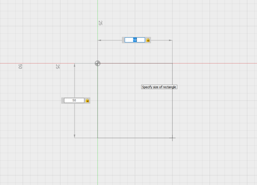
By using the constraints in the
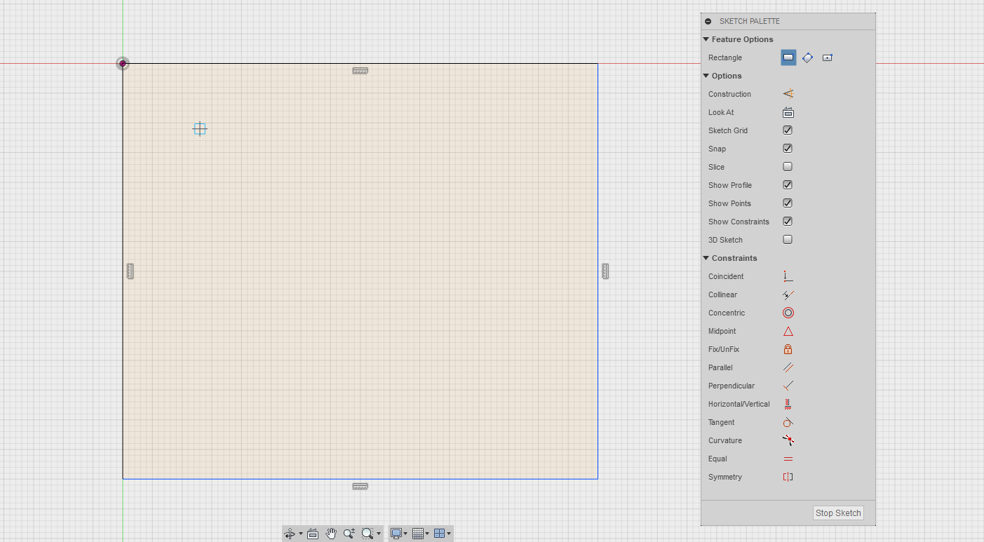
This sketching tool will be used quite often to create parts of the model in 2D which will later be transformed to 3D. Coming back to these sketches gives us the control of the final 3D design, since changing the parameters of th 2D dsign directly impacts the final model in 3D.
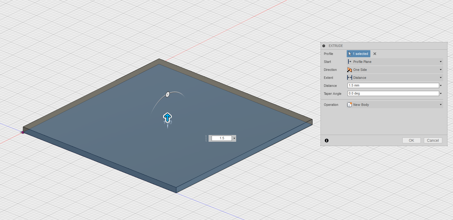
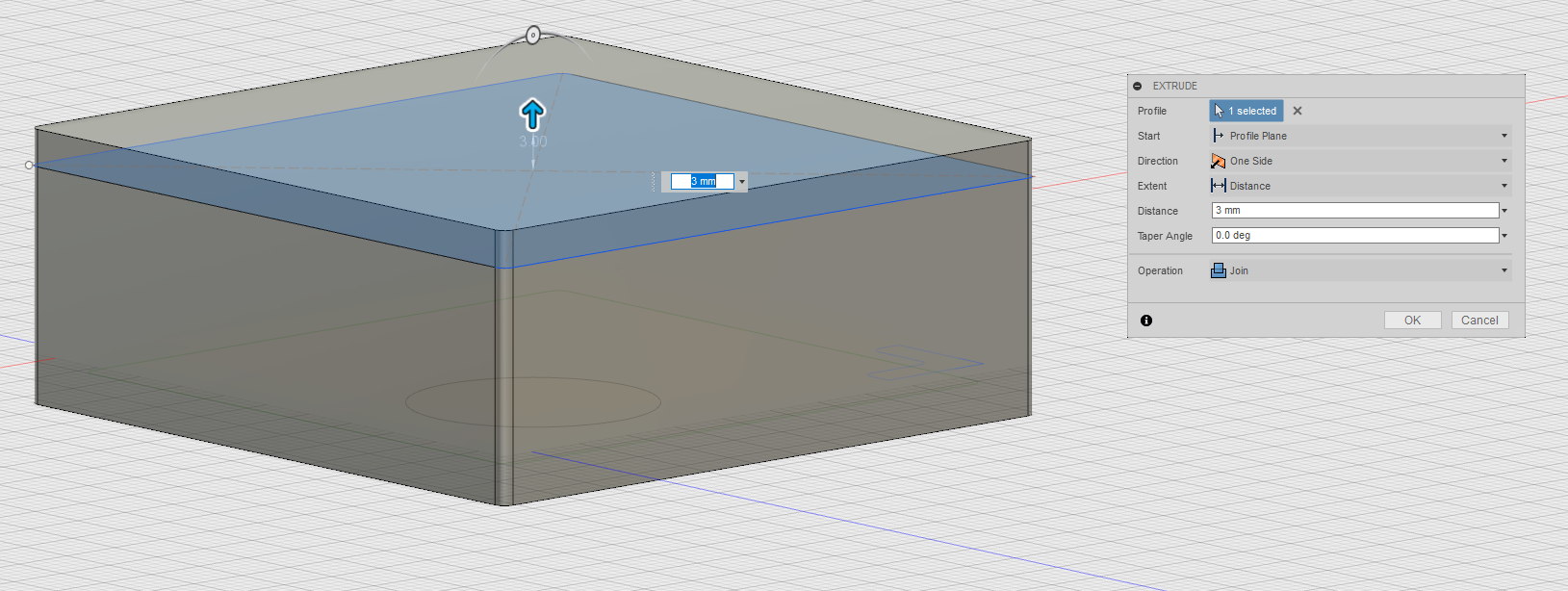
Extruding to 3D Design.
By using the hand
In order to build on top of the current design, it is handy to create a new
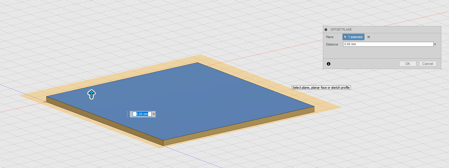
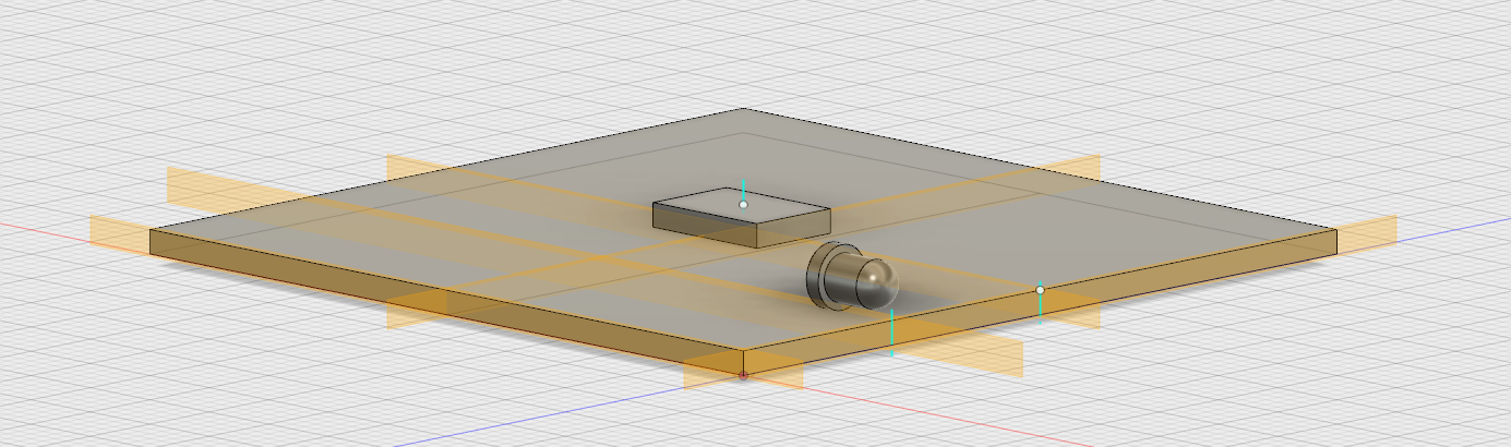
On top of this we will construct another sketch, which will include the models of the electronic components. In this case, the model of the Attiny84 microcontroller.
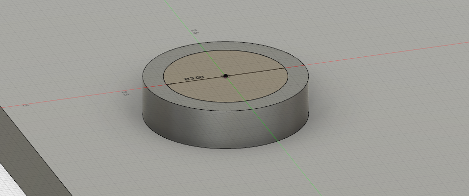
We continue by creating the model of the
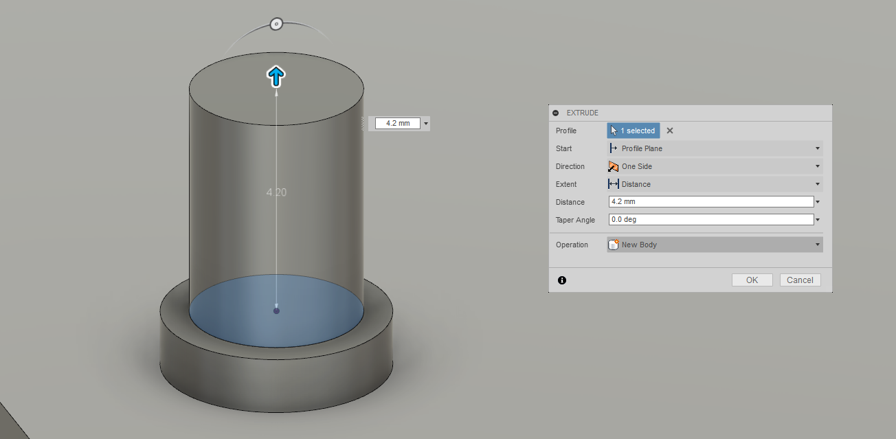
Then on top of that same 3D cylinder, another
And extruded to the size of the LED.
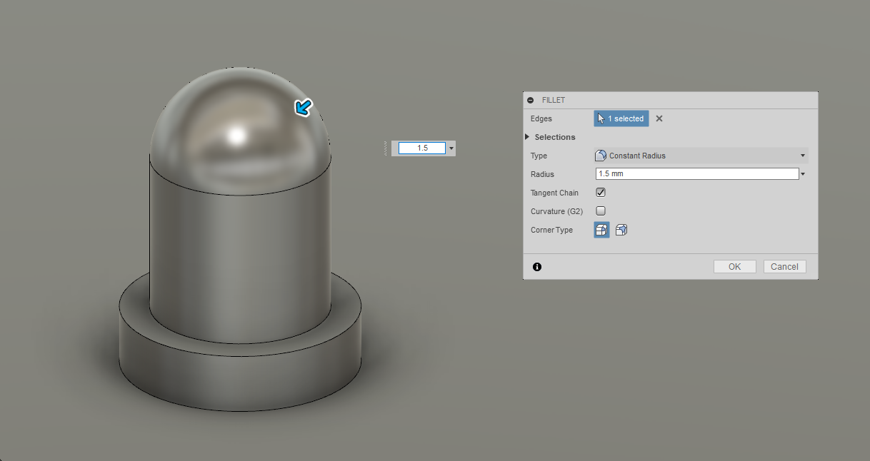
To create a roundy edge,
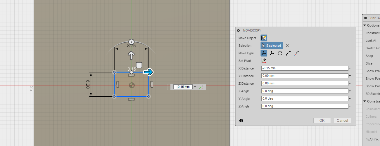
Manipulating Bodies.
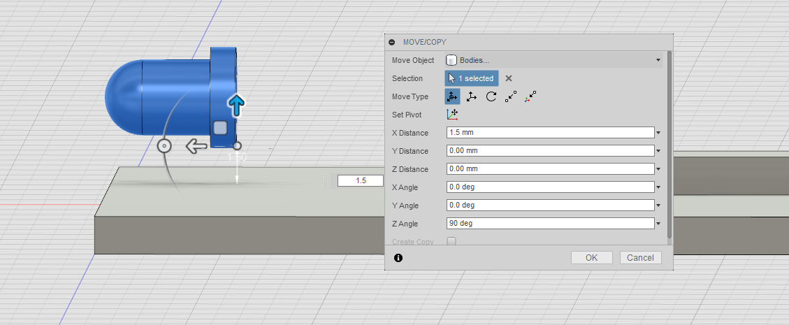
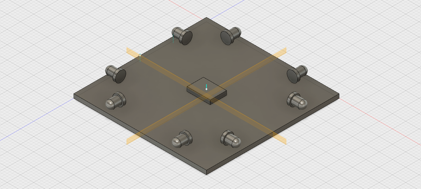
Our 3mm LED is succesfully created, we can take and reposition it in the desired way. For that all the bodies created are selected, and using second-click we choose
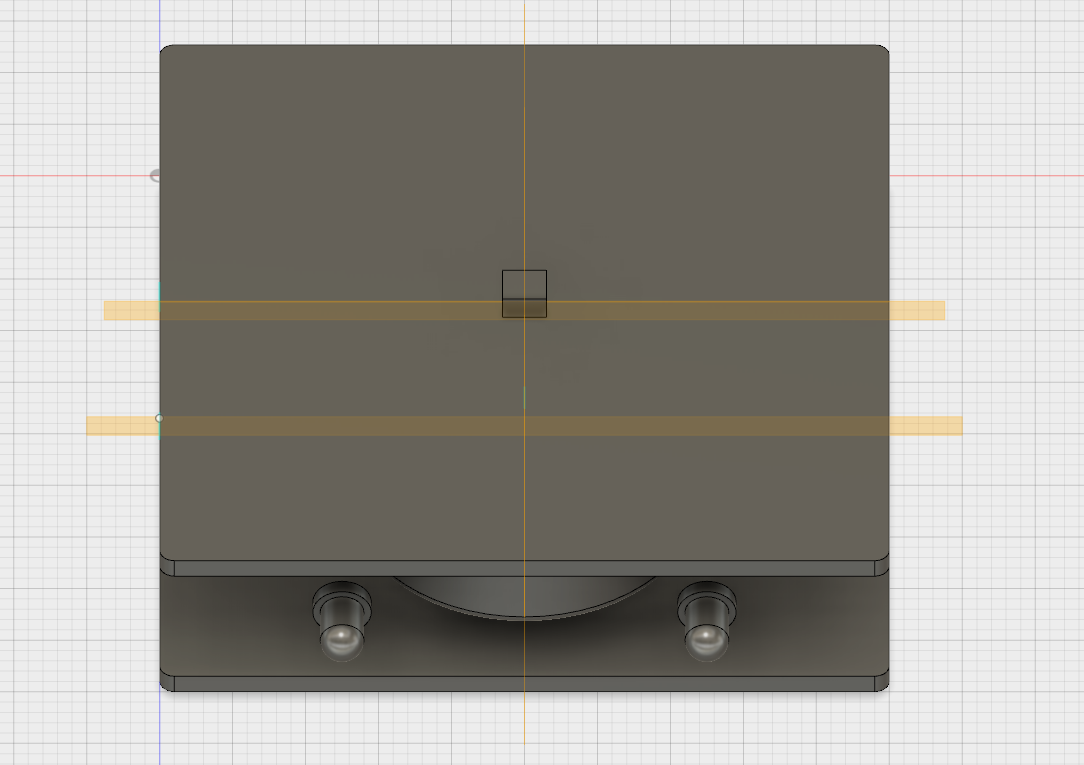
The end design will have 2 LEDs on each side of the cube. We would like to space them evenly. For that we need to create cross-planes, using which we can mirror the created objects. By going to
Now using the
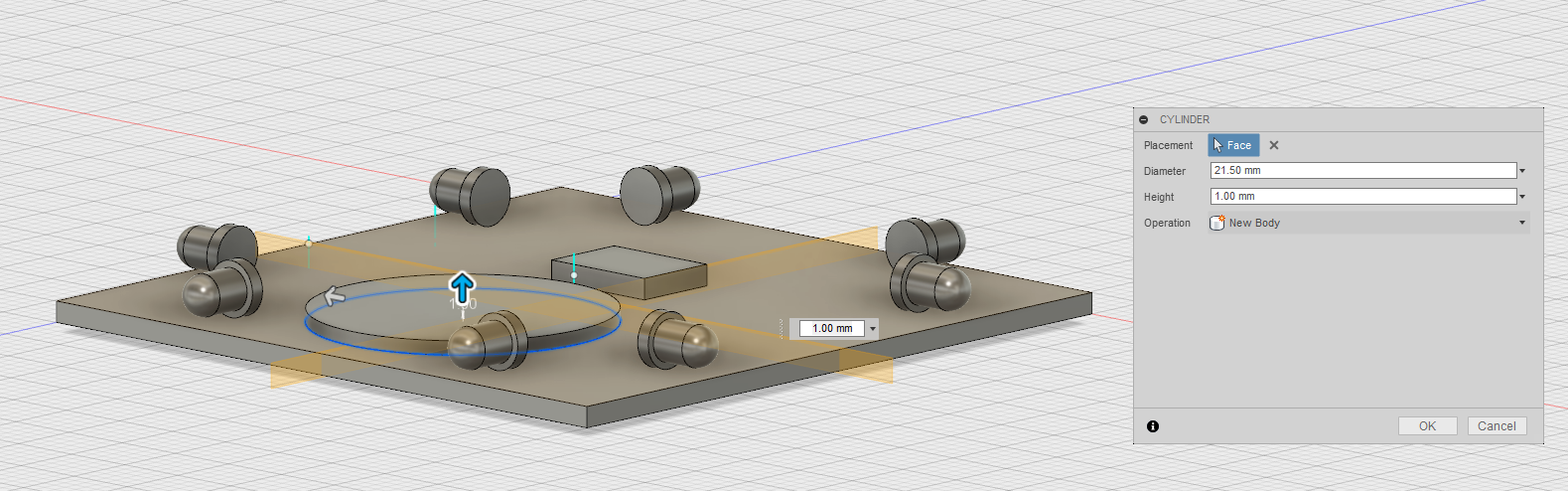
In a similar way we create the coin battery.
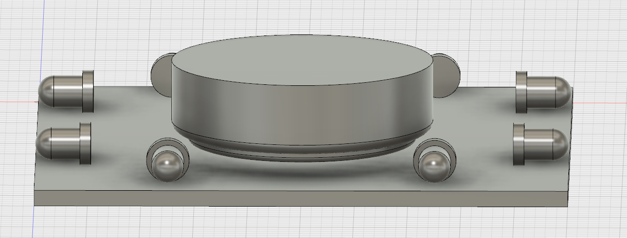
As well as create a board on top of our battery.
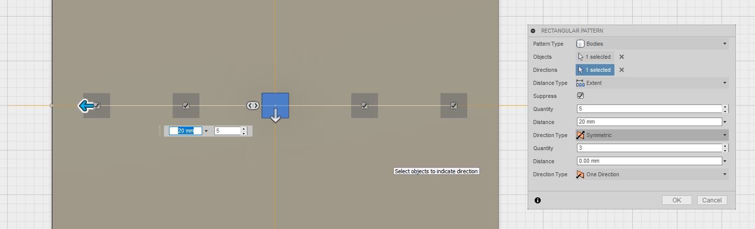
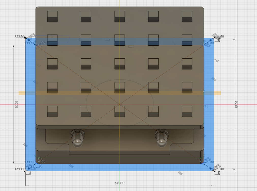
Patterned Bodies.
The top PCB will have a matrix of LEDs on it in forms of the cubes. Using the intersection of mid planes we create the first LED cube.
Now using the
We apply the same technique to the same created cube leds, already in the Y direction.
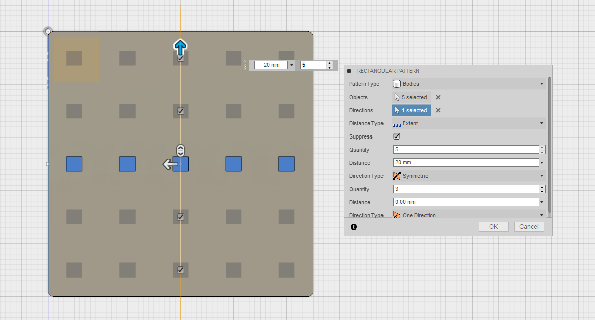
As a result we obtain a beautiful matrix of LED that is evenly spaced on top of our PCB.
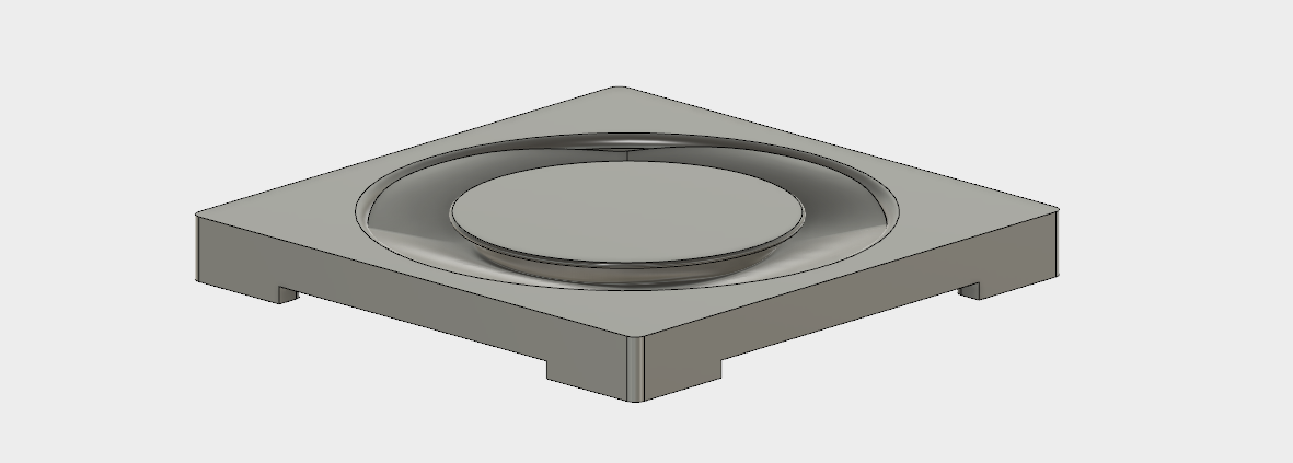
Modelling Bodies.
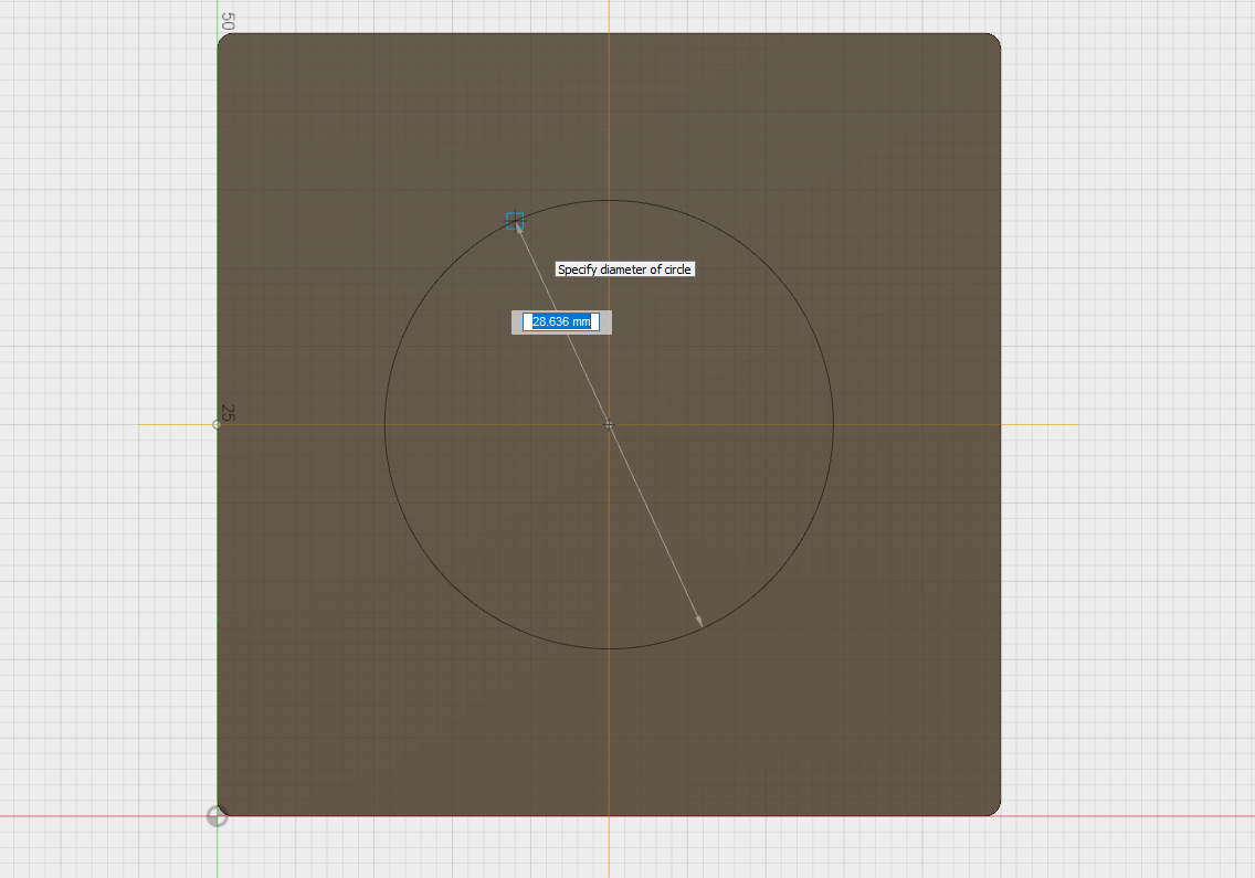
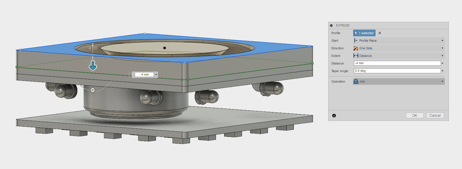
The current task is to create the case of our cube. The bottom lid will serve as an opening, having a circle using which the user can grab the lid and open it. For that, two other circles are created, one with smaller radius with about 2mm offest from the bottom pcb and the second with a bigger radius about 4mm ofset from the bottom pcb.
Using the
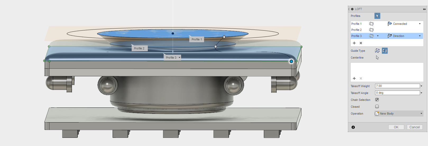
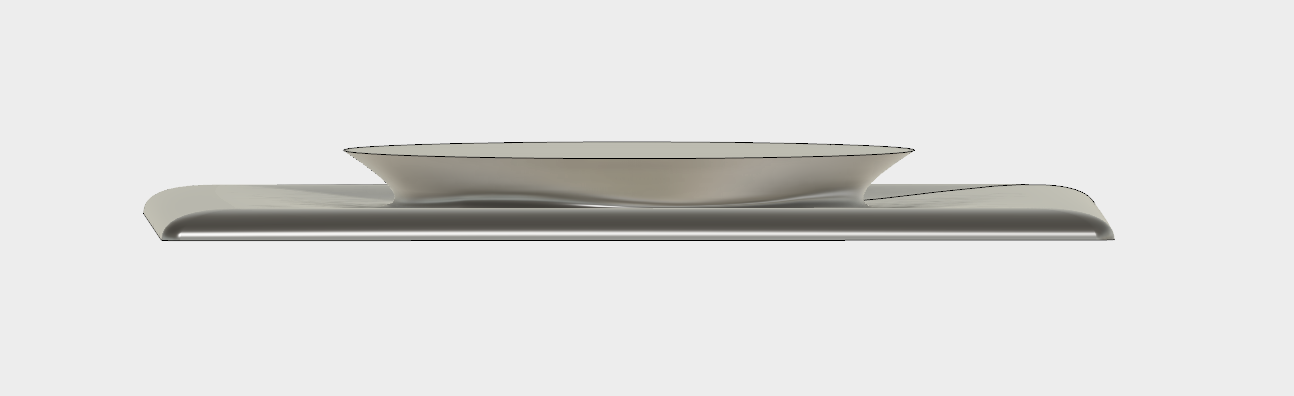
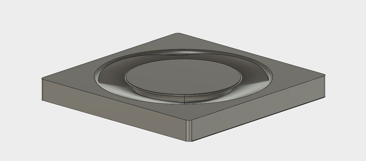
As a result we obtain this beautiful shape.
To seal the object, we extrude another Sketch, by using the
To create a good attachment of the bottom lid to the board, some corners are extruded.
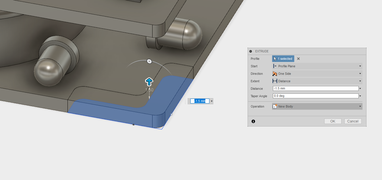
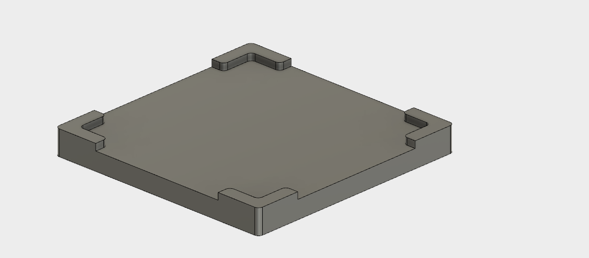
In a similar fashion, these corners are positioned on each of the board's corner and negatively extruded, which creates a
We endup with a nice cover, which has PCB mounting on top and opening lid on the bottom.
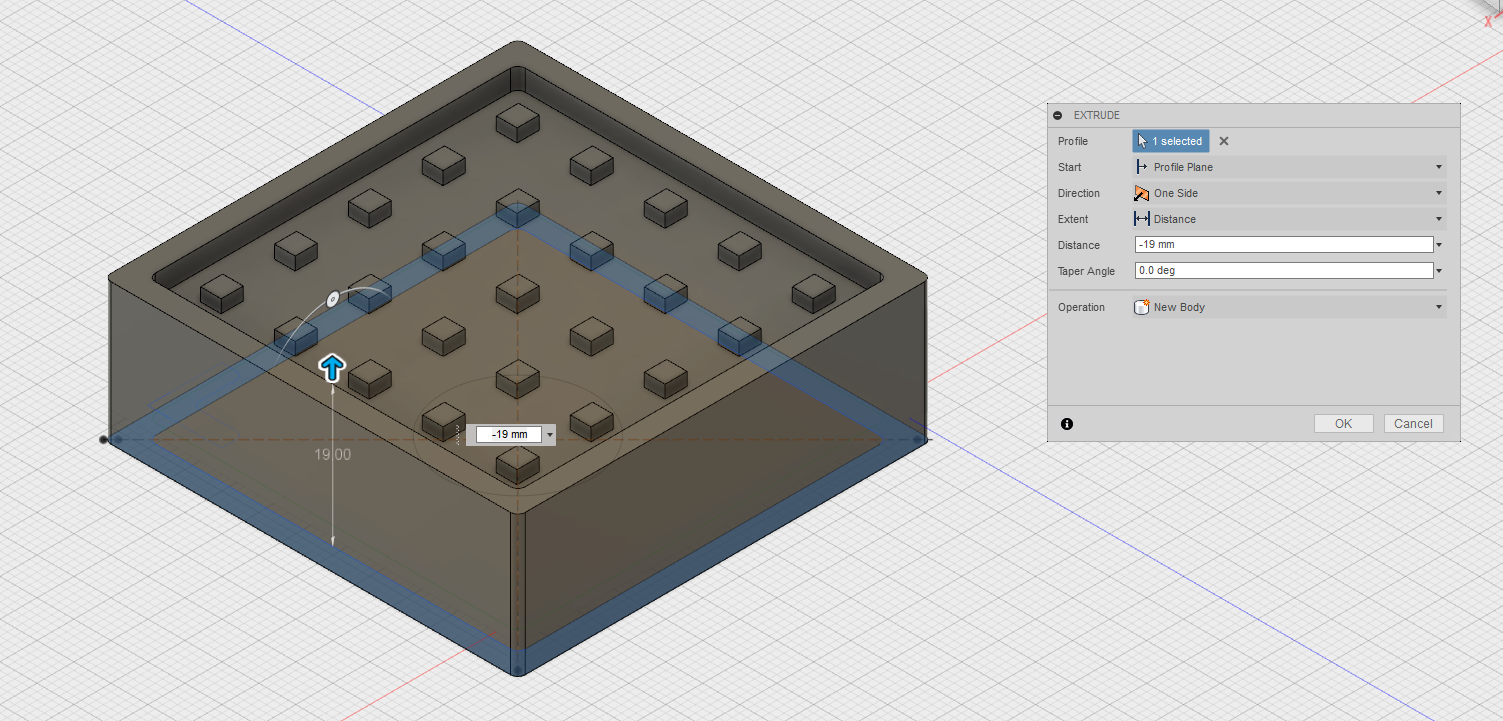
It is time to creat the outside case. For that, another sketch is created on the bottom lid. Two squares, one matching the size of the cube face and another being 3mm wider. This creates an area in between these two squares which allows for the casing to be extruded.
As a result we extrude the side walls which are a bit higher than our overall construction.
To finalize, we create another sketch on top of the current walls, to seal the deal.
To make an even more interesting shape, a smaller square is created with an offset height from the top lid.
Then we use again the
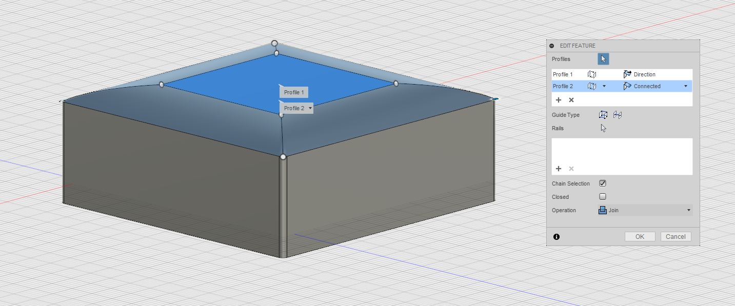
As a result we obtain a rough model of the final project, with all the electronic components, casing and overall built.
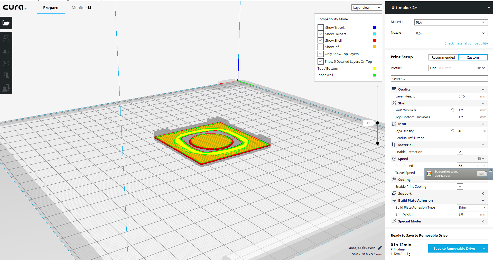
Exporting Models as 2D or 3D objects.
In order to export the 3D model's skethces in 2D, we directly click on the object's face and select
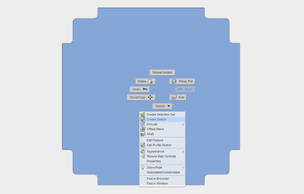
In the new sketches created we second-click the file and select
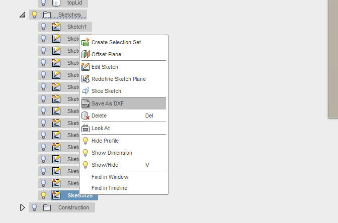
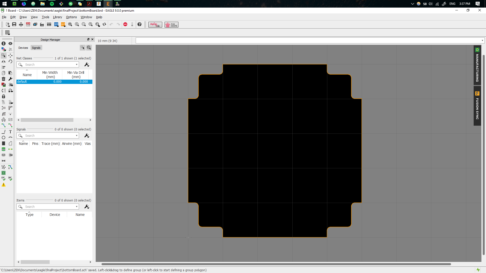
This can then be imported in Eagle to create the dimension of the board
Similarly, bodies can be exported as