For this week, I decided to put together a soft potentiometer.
The goal for this week is to add a sensor to a microcontroller board and read it. So I took my Bueno Board. I wanted to take my star board and first learn how to get it to recieve data (if it at all works). So to do with I decided to go with the basic first step in sensor related codiing - using a soft potentiometer. So I went online and looked for some code to help me along and discoverered a couple links:
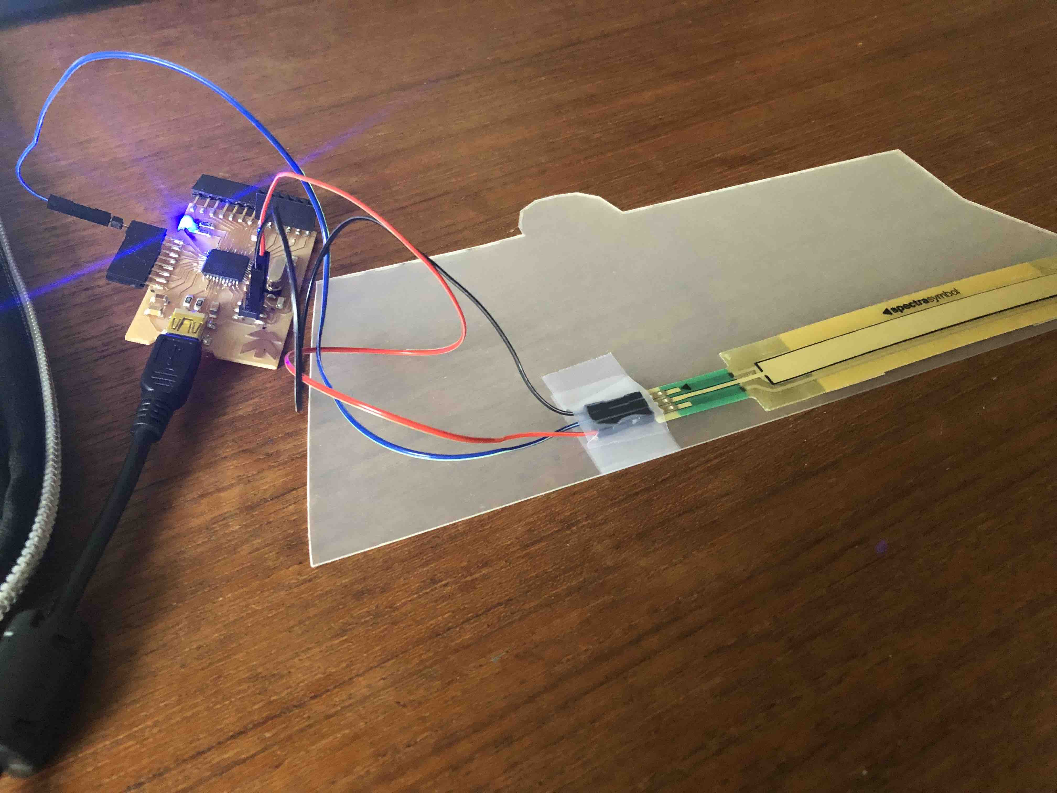
Quite honestly there is not much to say here. I simply followed the Soft Potentiometer - Hookup Guide I found and soldered on wires accordingly.Then I put it on a sheet of plastic so that it would stand out more but also be easier to manage and less prone to breakage.
On this website, I discovered the code below and instantly put it to the test.
/******************************************************************************
SoftPot_Example.ino
Example sketch for SparkFun's soft membrane potentiometer
  (https://www.sparkfun.com/products/8680)
Jim Lindblom @ SparkFun Electronics
April 28, 2016

- Connect the softpot's outside pins to 5V and GND (the outer pin with an arrow
indicator should be connected to GND).
- Connect the middle pin to A0.

As the voltage output of the softpot changes, a line graph printed to the
serial monitor should match the wiper's position.

Development environment specifics:
Arduino 1.6.7
******************************************************************************/
const int SOFT_POT_PIN = A0; // Pin connected to softpot wiper

const int GRAPH_LENGTH = 40; // Length of line graph

void setup()
{
  Serial.begin(9600);
  pinMode(SOFT_POT_PIN, INPUT);
}

void loop()
{
  // Read in the soft pot's ADC value
  int softPotADC = analogRead(SOFT_POT_PIN);
  // Map the 0-1023 value to 0-40
  int softPotPosition = map(softPotADC, 0, 1023, 0, GRAPH_LENGTH);

  // Print a line graph:
  Serial.print("<"); // Starting end
  for (int i=0; i<GRAPH_LENGTH; i++)
  {
    if (i == softPotPosition) Serial.print("|");
    else Serial.print("-");
  }
  Serial.println("> (" + String(softPotADC) + ")");

  delay(500);
}
But I didn't want to stop there, I wanted to see if I could control it. In other words, I wanted to see if I could control the LED on my board. So I took to trying to combine the fade example code and the softpot code to control the brightness of my LED. I did manage to get it to work, but not extremely efficiently. I believe this is for two reasons.
      /*SoftPot_Example.ino
Example sketch for SparkFun's soft membrane potentiometer
  (https://www.sparkfun.com/products/8680)
Jim Lindblom @ SparkFun Electronics
April 28, 2016

- Connect the softpot's outside pins to 5V and GND (the outer pin with an arrow
indicator should be connected to GND).
- Connect the middle pin to A0.

As the voltage output of the softpot changes, a line graph printed to the
serial monitor should match the wiper's position.

Development environment specifics:
Arduino 1.6.7
******************************************************************************/
const int SOFT_POT_PIN = A0; // Pin connected to softpot wiper

const int GRAPH_LENGTH = 40; // Length of line graph

int ledPin = 13; //pin 13 on sophie's bueno board
int brightness = 0;    // how bright the LED is
int fadeAmount = 10;    // how many points to fade the LED by

void setup()
{
  Serial.begin(9600);
  pinMode(SOFT_POT_PIN, INPUT);
  pinMode(ledPin, OUTPUT);

}

void loop()
{
  // Read in the soft pot's ADC value
  int softPotADC = analogRead(SOFT_POT_PIN);
  // Map the 0-1023 value to 0-40
 int softPotPosition = map(softPotADC, 0, 1023, 0, GRAPH_LENGTH);

 int brightnessLed = analogRead(SOFT_POT_PIN);

  // Print a line graph:
  //Serial.print("<"); // Starting end
 // for (int i=0; i<GRAPH_LENGTH; i++)
 //{
 //   if (i == softPotPosition) Serial.print("|");
 //   else Serial.print("-");
 // }
 // Serial.println("> (" + String(softPotADC) + ")");

Serial.println(softPotADC);


analogWrite(ledPin, brightness);
brightness = brightnessLed + fadeAmount;
if
(brightnessLed = 0 || brightnessLed >= 900)
{
    fadeAmount = -fadeAmount;
}

  delay(100);

if (softPotADC < 0.5)
{
 digitalWrite(ledPin, LOW);
}

else
{
  digitalWrite(ledPin, LOW);
}

}

      Sophie Kiarie, Fab Academy 2018
As you can see, it does bare some similarities to the origianl softpot code, but I got rid of some of the features as I felt like I didn't need them for this task.
Of course this does dig a bit into Outputs week, but I couldn't help myself! XD Plus it was a good starting point for my week 11 project. Because then I could test out my star board (if the touch sensor works).
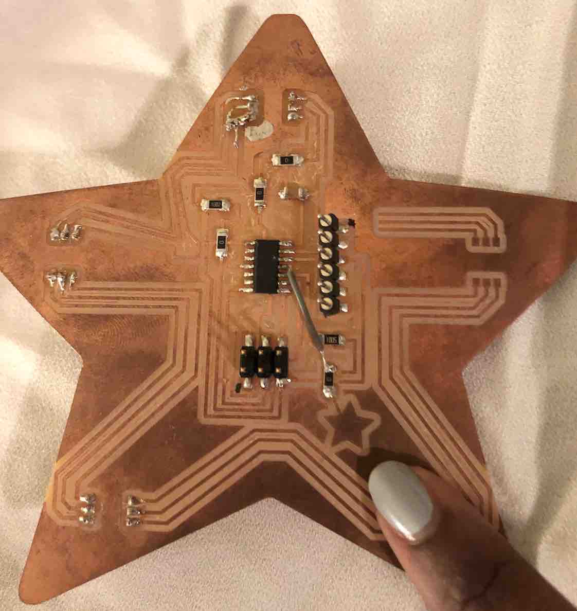
Unfortunetly, when trying to recreate it once more, my star board refused to work and I do not have the tools at hand to figure out why. The board has some issue when I try to upload the new (but old really) soft pot code. The star blinks/flashes but that is about all the communication I can get from it. I see the problem arise when I connect the wire to VCC. (see video below). Which is dissapointing. I believe that the problem is that the board is short circuiting as I later also attempted to use my final project battery to connect directly. I believe that perhaps during transport between the UK and Germany the board got spoilt somehow. However I do know how to set things up and what needs to go where....
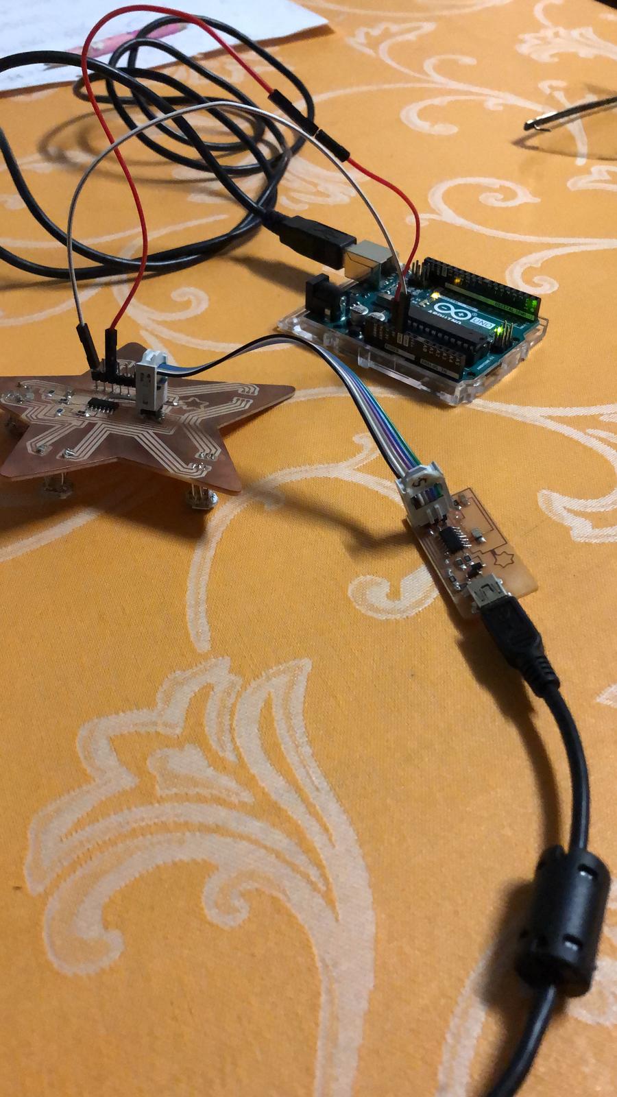
In order to setup the star board to test it's touch sensor, first things first you will need:
Next you of course hook everything up and open up arduino. The following code still applies here except the pin is different and the way you upload is too.
        const int touchsensor = 7; // Pin connected to softpot wiper

const int GRAPH_LENGTH = 40; // Length of line graph

void setup()
{
  Serial.begin(9600);
  pinMode(touchsensor, INPUT);
}

void loop()
{
  // Read in the soft pot's ADC value
  int touchsensorADC = analogRead(touchsensor);
  // Map the 0-1023 value to 0-40
  int touchsensorPosition = map(softPotADC, 0, 1023, 0, GRAPH_LENGTH);

  // Print a line graph:
  Serial.print("<"); // Starting end
  for (int i=0; i<GRAPH_LENGTH; i++)
  {
    if (i == softPotPosition) Serial.print("|");
    else Serial.print("-");
  }
  Serial.println("> (" + String(touchsensorADC) + ")");

  delay(500);
}


Sophie Kiarie, Fab Academy 2018
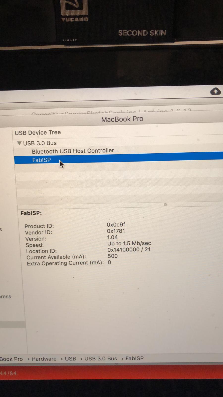
Now in order to get things done right, you need to go to tools and make sure that:
Now back to Arduino, you want to go to "Sketch" then "Upload using Programmer" and the sketch will upload to your star board through the programmer. Now this would be the part I would have celebrated but unforuntely mine still did not work.
In the video below, you see me testing a simple blink code on arduino, still using the same methods as above, but just a different code. It was to see if there was a problem with my code or if it was the board. As you can see, Arduino threw me an error saying it had an error when uploading the sketch.
As much as this has annoyed me, I can at least come out of this knowing I know how to do it as I had used it for mutliple projects (Machine Week, Wildcard Week and Final Project in order to each time read the data and manipulate it :) .
This weeks homework: