Because I was behind on week 6, it put me behind for week 8.
I have done the board now and it is all soldered and I have clued it in that it is a board (I did burn bootloader). Initially I had countless unsolveable and still undiscovered issues with my programmer board. Luiz and I attempted to check the current flow in it, the soldering up close using a microscope, but were unable to figure out the reason as to why it refuses to be a programmer. We had a look at the "Trouble Shooting Short Circuits" section of FabISP: Electronics Production page, following each of the recommended steps to test and find out why the board wouldn't work.
This meant I had to re-do my old board. But luckily after countless programmers hitting the trash dump, I got one working. And that was a last attempt thing. YAY!
First things first, I needed to teach my board to become and embody the true spirit of what it means to be a board!
To do this, I used my programmer, and under "tools" selected the "USBtinyISP" in the programmer drop down then clicked "burn bootloader".
Once that was done, I searched for a code to use.
For this section, I went onto Arduino and looked for the Button code.
        /*
  Button

  Turns on and off a light emitting diode(LED) connected to digital pin 13,
  when pressing a pushbutton attached to pin 2.

  The circuit:
  - LED attached from pin 13 to ground
  - pushbutton attached to pin 2 from +5V
  - 10K resistor attached to pin 2 from ground

  - Note: on most Arduinos there is already an LED on the board
    attached to pin 13.

  created 2005
  by DojoDave <http://www.0j0.org>
  modified 30 Aug 2011
  by Tom Igoe

  This example code is in the public domain.

  http://www.arduino.cc/en/Tutorial/Button
*/

// constants won't change. They're used here to set pin numbers:
const int buttonPin = 7;     // the number of the pushbutton pin
const int ledPin =  8;      // the number of the LED pin

// variables will change:
int buttonState = 0;         // variable for reading the pushbutton status

void setup() {
  // initialize the LED pin as an output:
  pinMode(ledPin, OUTPUT);
  // initialize the pushbutton pin as an input:
  pinMode(buttonPin, INPUT);
}

void loop() {
  // read the state of the pushbutton value:
  buttonState = digitalRead(buttonPin);

  // check if the pushbutton is pressed. If it is, the buttonState is HIGH:
  if (buttonState == HIGH) {
    // turn LED on:
    digitalWrite(ledPin, HIGH);
  } else {
    // turn LED off:
    digitalWrite(ledPin, LOW);
  }
}
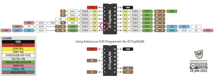
I used this pinout image I got from google images to figure out which pin my switch and LED corresponded to.
Equipment Required:
Then I decided to try to expand. So I went online to look for a way to get Processing and Arduino chatting. AND I DID! Check out this link:
How to Make Arduino and Processing IDE Comminicate
        int softPot_pin = A0;   // Initializing the Potentiometer pin

int pot_output;     // Declaring a variable for potentiometer output


void setup ( ) {

pinMode(LED_BUILTIN, OUTPUT); // Declaring the LED pin as output pin

Serial.begin(9600);       // Starting the serial communication at 9600 baud rate

}

void loop ( ) {

pot_output = analogRead (LED_BUILTIN); // Reading from the potentiometer

int mapped_output = map (pot_output, 0, 1023, 0, 255); // Mapping the output of potentiometer to 0-255 to be read by the Processing IDE

Serial.println (mapped_output);     // Sending the output to Processing IDE


if (Serial.available ( ) > 0) {   // Checking if the Processing IDE has send a value or not

char state = Serial.read ( );    // Reading the data received and saving in the state variable

if(state == '1')             // If received data is '1', then turn on LED

{

digitalWrite (LED_BUILTIN, HIGH);
delay(1000);

}

if (state == '0') {     // If received data is '0', then turn off led

digitalWrite (LED_BUILTIN, LOW);
delay(1000);
}

}

delay(50);

}
This link has the original code
I followed instructions and it led me to this when I used my softpot instead of a potentiometer
WARNING!!!The video has flashing images!
I did attempt to get it to react with the button board, but that resulted in me recieving no reaction in the processing code when I hit run.....something I want to try see if I can get working later on though as that would be quite cool.
This is the code I wrote to try to attempt this:
int buttonPin = 7;     // the number of the pushbutton pin
int buttonPin_output;     // Declaring a variable for potentiometer output


void setup ( ) {

pinMode(LED_BUILTIN, OUTPUT); // Declaring the LED pin as output pin

Serial.begin(9600);       // Starting the serial communication at 9600 baud rate

}

void loop ( ) {

buttonPin_output = analogRead (buttonPin); // Reading from the potentiometer

int mapped_output = map (buttonPin_output, 0, 1023, 0, 1); // Mapping the output of potentiometer to 0-255 to be read by the Processing IDE

Serial.println (mapped_output);     // Sending the output to Processing IDE


if (Serial.available ( ) > 0) {   // Checking if the Processing IDE has send a value or not

char state = Serial.read ( );    // Reading the data received and saving in the state variable

if(state == '1')             // If received data is '1', then turn on LED

{

digitalWrite (LED_BUILTIN, HIGH);

}

if (state == '0') {     // If received data is '0', then turn off led

digitalWrite (LED_BUILTIN, LOW);

}

}

delay(50);

}

Sophie Kiarie, Fab Academy 2018
But at least thanks to the group work I got to see other programs in action, where we learnt to use Raspberry Pi to run an LED flashing programme in Python.
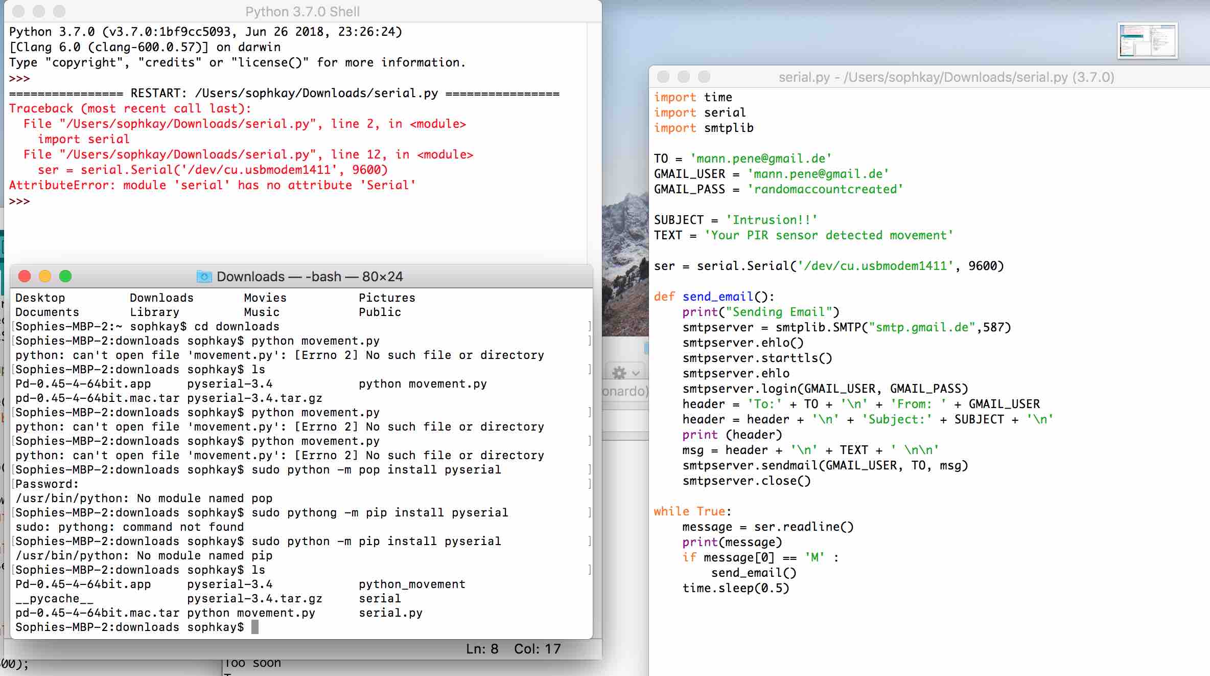
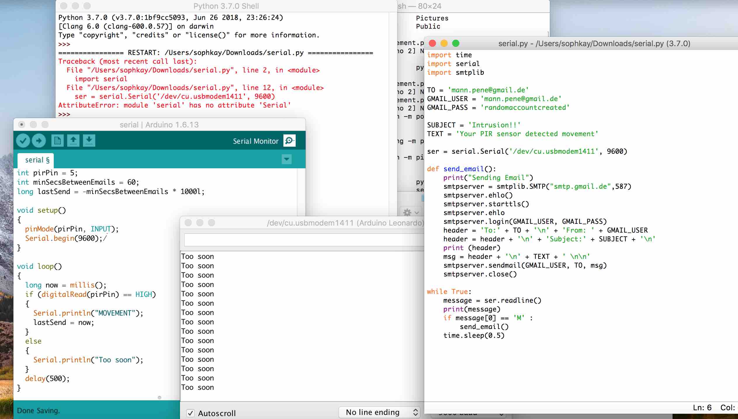
I too attempted to get Arduino to talk to Python using the code I found on this website:
How to Make Arduino and Processing IDE CommunicateUnfortunetly, I could not figure out what was going wrong. The issue occured in Python and I believe it's something to do with my lack of knowledge of my computer and the way it works. I initially had issues getting it to work, but then when I switched to my admin account it began to work better. Except for the Python error message (see below). I tried to check online about the error message but could not figure it out in the end after spending an hour.
But the Arduino code did work the way it was meant to, which is how I know that the problem, other than obviously the Python's error message, is with Python.
Downloadable Link to Microcontroller Datasheet:
Now, this microcontroller Datasheet isn't exactly, to me, the most fascinating couple pages. BUT, darn it is it helpful. It definetly wasn't something that I found myself reading back to front, but more like you would read a dictionary; when you are searching for something you look it up, potentially do more research on it, then go back to whatever it is you were doing.
What was quite interesting, although it makes sense but I suppose it was one of those things you don't really think about and then when you do you have that "ohhhhh, yeah ok makes sense" moments...just me? Anyways, I am referring here to the sleep mode. It is something I didn't quite think exsisted but now that I know, I know it makes sense to have it. It was nice to see the different ways available to access them on the chip. Find on page 33 - 34. I found this and thought this quite interesting because it isn't something I would've considered. This is probably because I have never had to actually think about it since most machines in the past I have used them and they were pre-made, so things such as sleep mode and power down were built in...:
Minimizing Power Consumption
"There are several issues to consider when trying to minimize the power consumption in an AVR controlled system. In general, sleep modes should be used as much as possible, and the sleep mode should be selected so that as few as possible of the device’s functions are operating. All functions not needed should be disabled. In particular, the following modules may need special consideration when trying to achieve the lowest possible power consumption."
p. 35
On thing I would love to learn more about is the "Watchdog Timer" as it is mentioned quite a lot in that section but I still don't quite understand what it is or does. I can only assume that since it is mentioned quite a bit, that it is important and or it is very useful.
I also thought it was quite useful/nice to see the diagrams they had in there as the last time I had seen or drawn one was in I.B. physics or M.Y.P. physics, and that is a VERY long time ago. It was nice to be reminded what they look like but also now see a bit more complex ones. It sort of helped me for future board designing when I had a hard time figuring out what component was what in eagle when the name of the component was too vague for me to understand and the picture not something I'd seen before.
This weeks homework: