This week took a bit to understand at first, especially since I had missed the time it was taught. But then when I got to see Luiz's video on his site, it made more sense as what this week was about. It's always like that isn't it??
I also used Luiz's code on his website as a guideline to help me but also breakdown what I needed to do as a basis and then build even more from there to make it my own work.
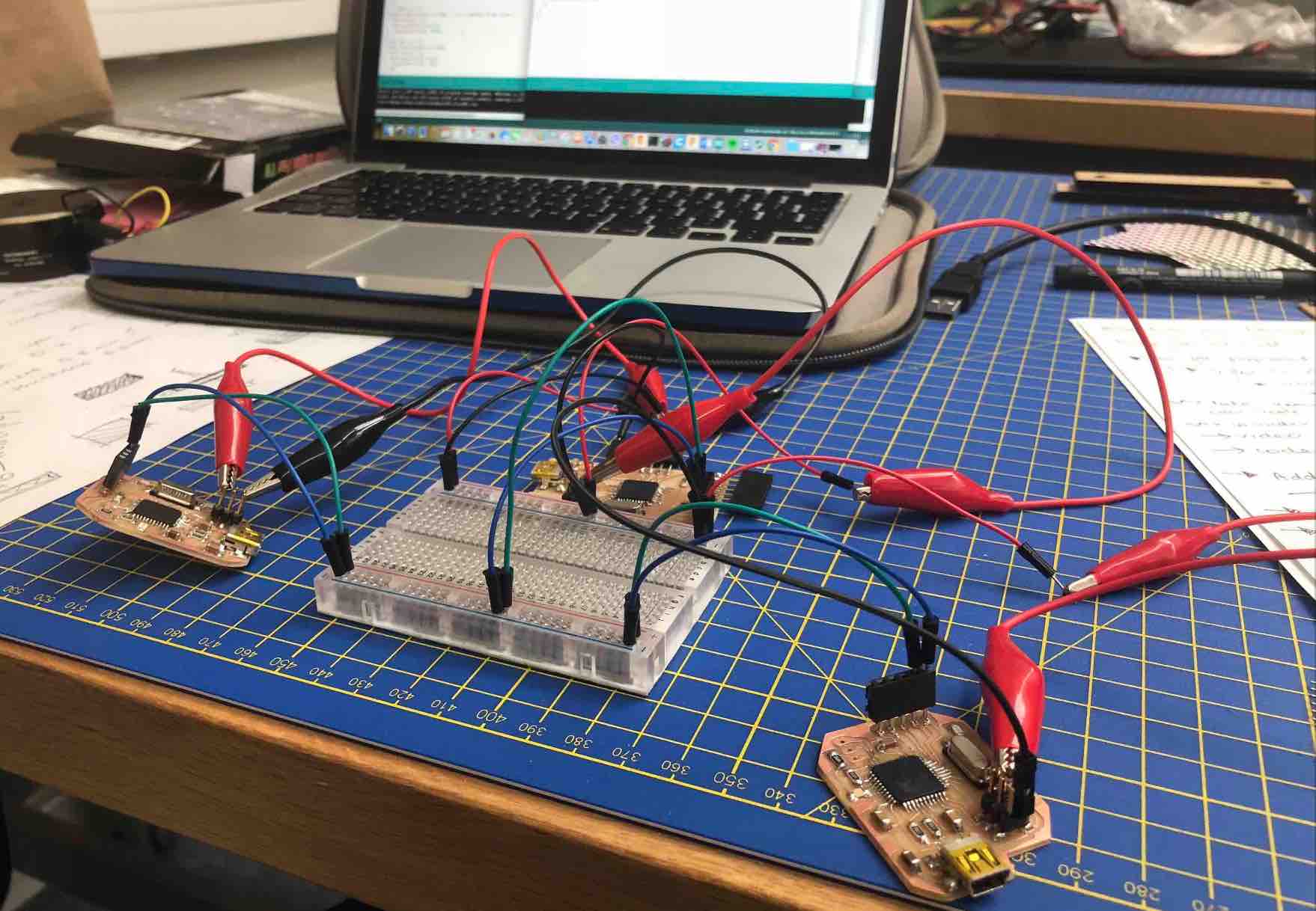
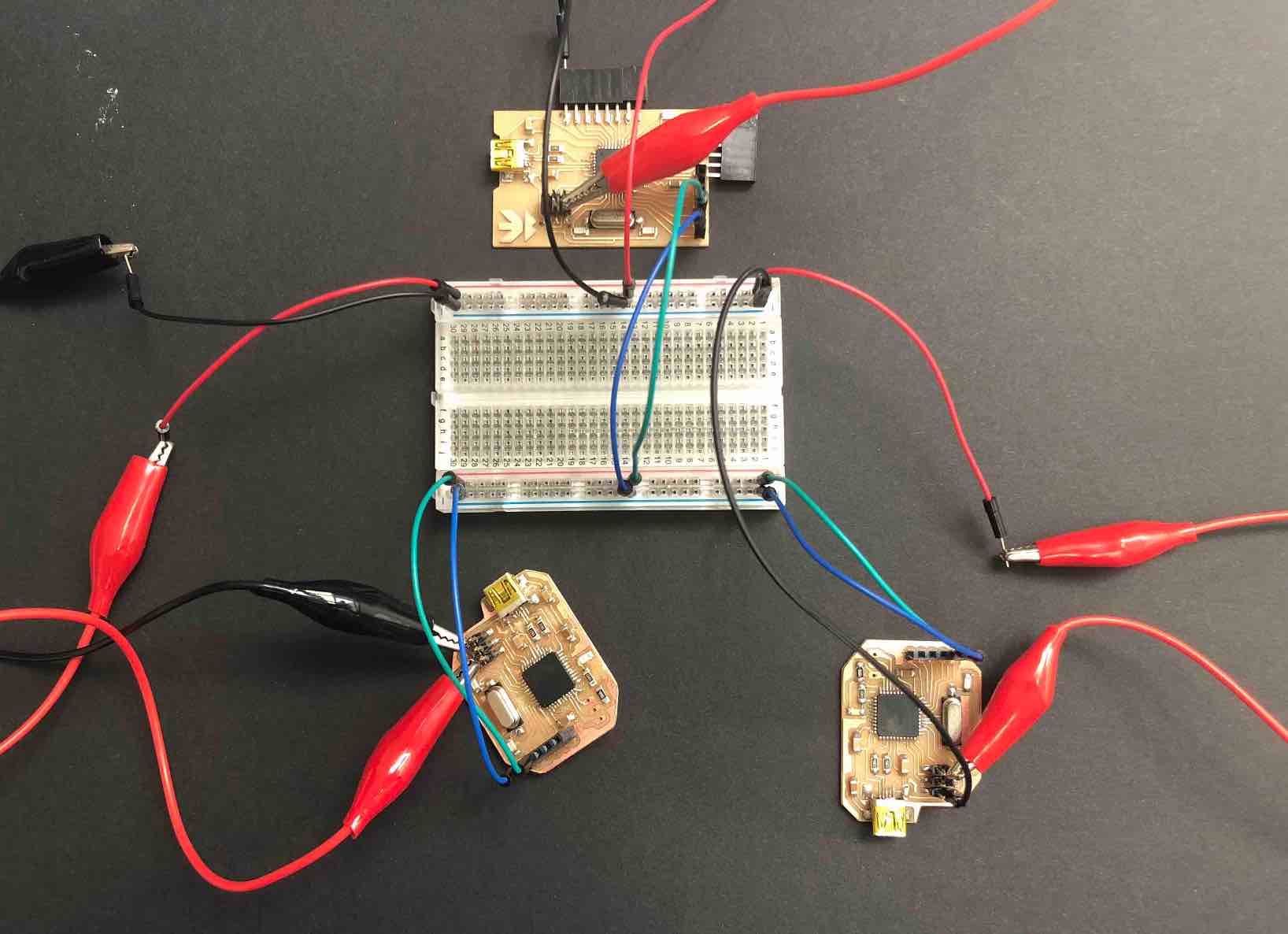
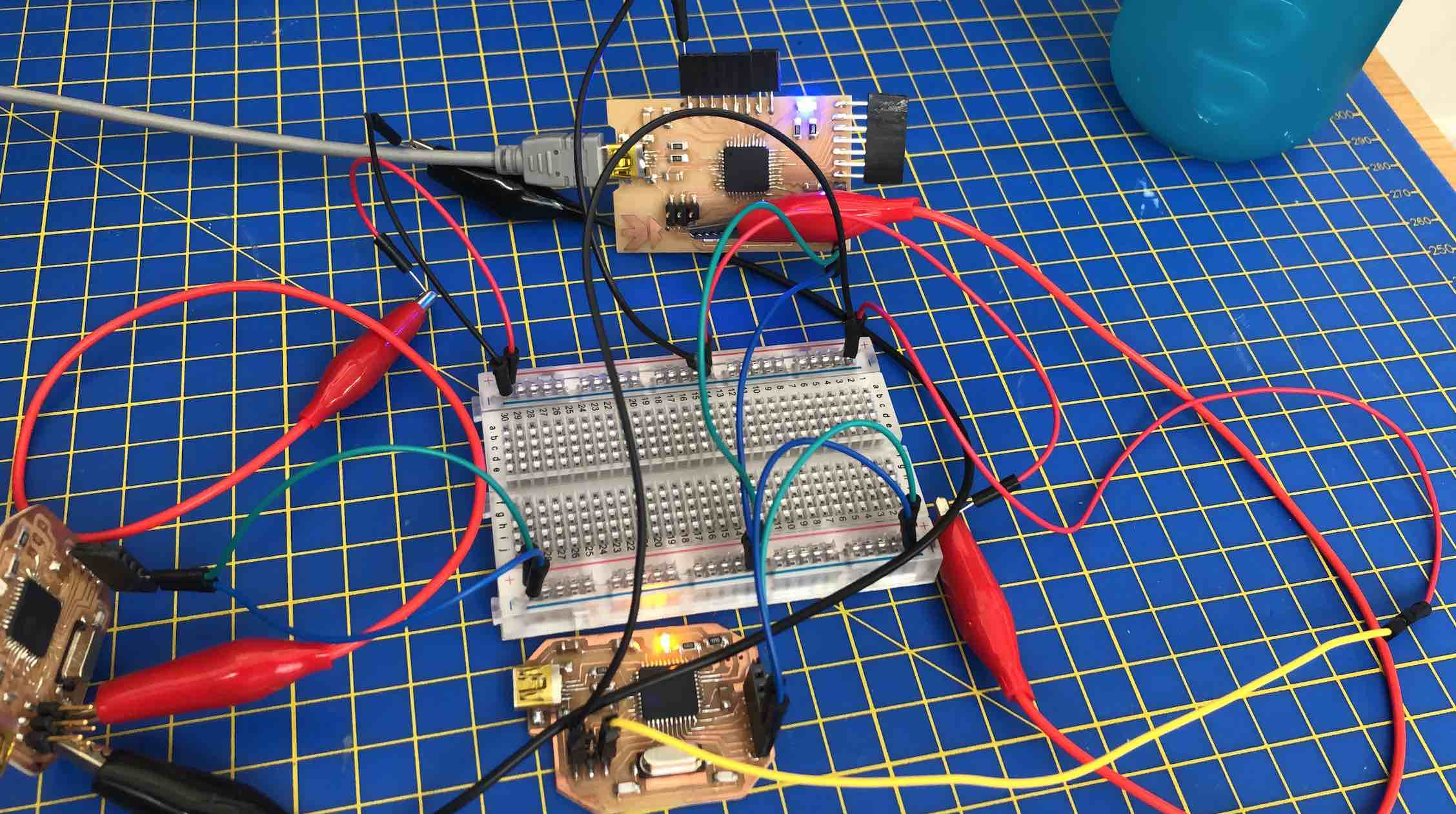
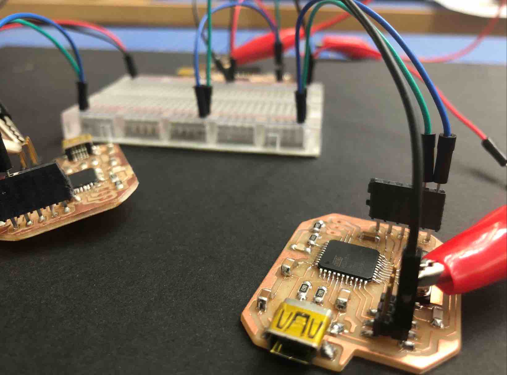
At the lab because there are so many of use I did end up having to improvise a little as we were running out of M.F. wire cables, so I used a mix between crocodile clips and male wires to wire up my boards, which occasionally presented some problems if they weren't placed correctly. In the end I did manage to sacavenge one more M.F. wire, which has solved the wiring issue I had between the slave 02 board and the other cables. I now only have one crocodile cable.
Great question. I know it but I don't. Or rather I did not. I used to study physics so I know what it means and stands for but when it came to this, no idea. So I did a bit or snooping around and researching.
I found this here on this website:
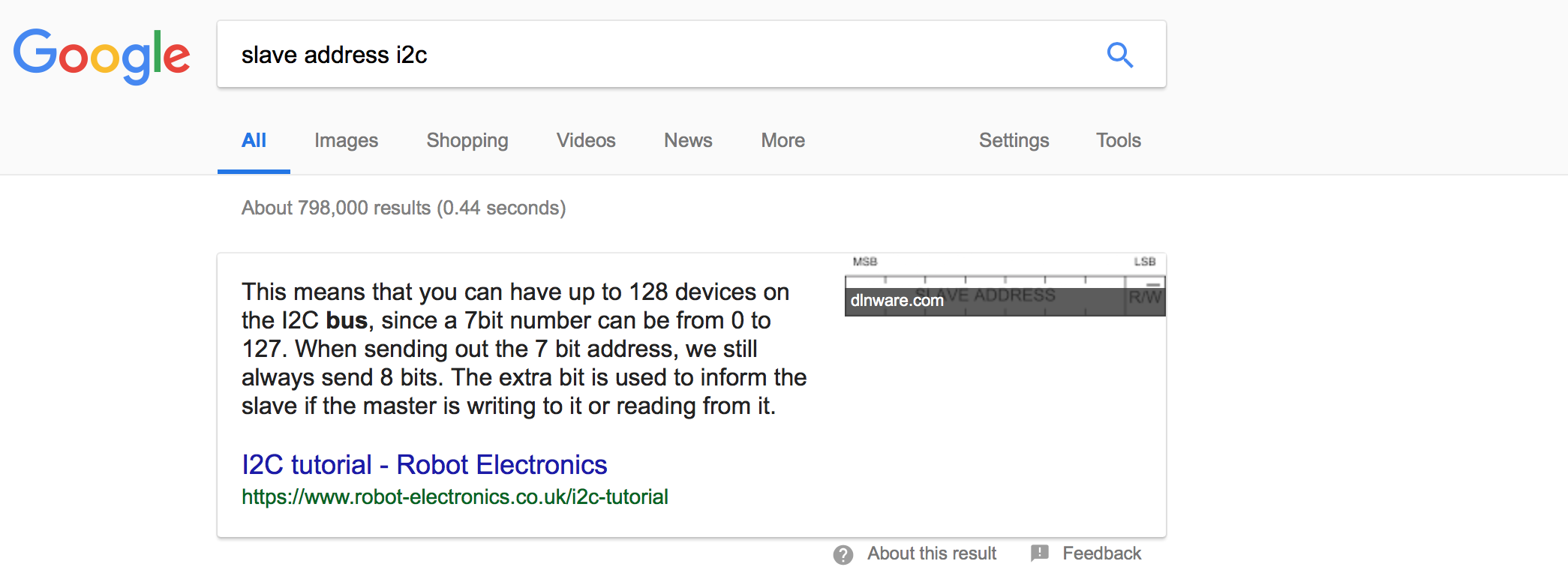
"I2C is a serial protocol for two-wire interface to connect low-speed devices like microcontrollers, EEPROMs, A/D and D/A converters, I/O interfaces and other similar peripherals in embedded systems. It was invented by Philips and now it is used by almost all major IC manufacturers. Each I2C slave device needs an address – they must still be obtained from NXP (formerly Philips semiconductors).
I2C bus is popular because it is simple to use, there can be more than one master, only upper bus speed is defined and only two wires with pull-up resistors are needed to connect almost unlimited number of I2C devices. I2C can use even slower microcontrollers with general-purpose I/O pins since they only need to generate correct Start and Stop conditions in addition to functions for reading and writing a byte.
Each slave device has a unique address. Transfer from and to master device is serial and it is split into 8-bit packets. All these simple requirements make it very simple to implement I2C interface even with cheap microcontrollers that have no special I2C hardware controller. You only need 2 free I/O pins and few simple i2C routines to send and receive commands.
The initial I2C specifications defined maximum clock frequency of 100 kHz. This was later increased to 400 kHz as Fast mode. There is also a High speed mode which can go up to 3.4 MHz and there is also a 5 MHz ultra-fast mode."
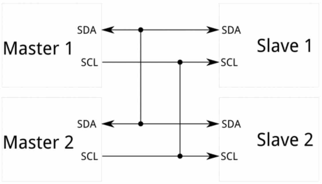
In some more simpler words; The Inter-intergrated Cicuit (I2C) Protocol is a protocol that allows multiple "slave" digital intergrated chips to talk to one (or more) "master" chips.
This site is so helpful. It was kind of like reading a cheatsheet. It explained to me which pins I would need to have hooked up (SDA and SCL - serial clock) and both would need to be pulled up with a resistor to VDD.
It also taught me that because its specifications are flexible it can not only communicate with slow decides and high speed modes, but any microcontroller can communicate with I2C devices. This made me wonder if I could potentially then use a attiny 44 and a atmega32U microcontrollers to communicate with one another. Nothing complex some very simple code, perhaps like the below ones. This would be something worth and fun testing out.
I will be honest, this is a question I did not even consider until I was doing research and stubmled upon this link and I must say, only some of it makes sense to me really but it makes sense enough that I understand it...:
Why not just use Serial UART Ports?
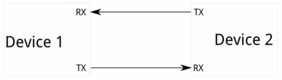
"Because serial ports are asynchronous (no clock data is transmitted), devices using them must agree ahead of time on a data rate. The two devices must also have clocks that are close to the same rate, and will remain so–excessive differences between clock rates on either end will cause garbled data.
Asynchronous serial ports require hardware overhead–the UART at either end is relatively complex and difficult to accurately implement in software if necessary. At least one start and stop bit is a part of each frame of data, meaning that 10 bits of transmission time are required for each 8 bits of data sent, which eats into the data rate.
Another core fault in asynchronous serial ports is that they are inherently suited to communications between two, and only two, devices. While it is possible to connect multiple devices to a single serial port, bus contention (where two devices attempt to drive the same line at the same time) is always an issue and must be dealt with carefully to prevent damage to the devices in question, usually through external hardware.
Finally, data rate is an issue. While there is no theoretical limit to asynchronous serial communications, most UART devices only support a certain set of fixed baud rates, and the highest of these is usually around 230400 bits per second."
Sure but what about SPI?
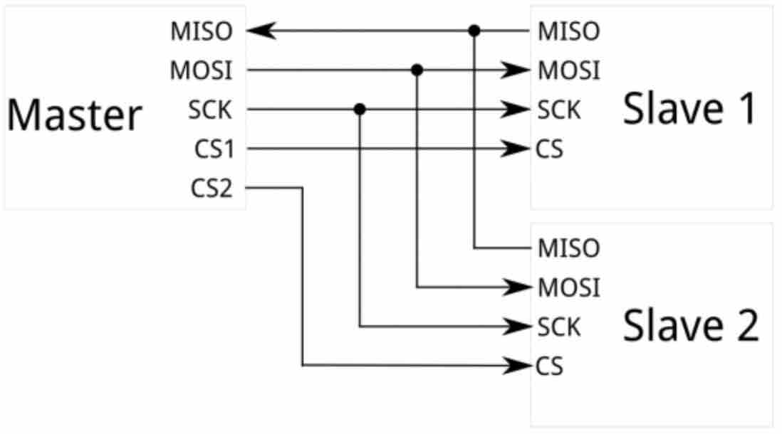
"The most obvious drawback of SPI is the number of pins required. Connecting a single master to a single slave with an SPI bus requires four lines; each additional slave requires one additional chip select I/O pin on the master. The rapid proliferation of pin connections makes it undesirable in situations where lots of devices must be slaved to one master. Also, the large number of connections for each device can make routing signals more difficult in tight PCB layout situations. SPI only allows one master on the bus, but it does support an arbitrary number of slaves (subject only to the drive capability of the devices connected to the bus and the number of chip select pins available).
SPI is good for high data rate full-duplex (simultaneous sending and receiving of data) connections, supporting clock rates upwards of 10MHz (and thus, 10 million bits per second) for some devices, and the speed scales nicely. The hardware at either end is usually a very simple shift register, allowing easy implementation in software."
Simply put, I2C picks up where those two fail. It takes (and because I could not phrase it better) the best of both worlds requiring just 2 main wires
I started off with this following code (see below)
        //i2c JalapinoMaster code (to Luizino and "Hello, World - I'm Luiz" boards)
#include  <Wire.h>

void setup()
{
Serial.begin(9600);
Wire.begin();
}

void loop()
{
  while(Serial.available())

{char c = Serial.read();

  if(c == '1')
  { Wire.beginTransmission(5);
    Wire.write('H');
    Wire.endTransmission();
    digitalWrite(13, HIGH);
        }
  else if(c == '2')
  { Wire.beginTransmission(5);
    Wire.write('L');
    Wire.endTransmission();
     digitalWrite(13, LOW);
    }

     if(c == '3')
  { Wire.beginTransmission(6);
    Wire.write('H');
    Wire.endTransmission();
     digitalWrite(13, HIGH);         }

  else if(c == '4')
  { Wire.beginTransmission(6);
    Wire.write('L');
    Wire.endTransmission();
     digitalWrite(13, LOW);
    }

    if(c == '5')
    {digitalWrite(13,LOW);
    }

    else if(c == '6')
    {digitalWrite(13,LOW);
    }

    if(c == '7')
    { Wire.beginTransmission(6); //6 is address of the slave 2
    Wire.write('H');
    Wire.endTransmission();
    digitalWrite(13, HIGH);   //turn the LED on (HIGH is the voltage level)
    delay(1000);
    digitalWrite(13, LOW);
    delay(1000);
    }

    else if(c == '8')
    { Wire.beginTransmission(6);
    Wire.write('L');
    Wire.endTransmission();
    digitalWrite(13, HIGH); // turn the LED on (HIGH is the voltage level)
    delay(1000);   // wait for a second
    digitalWrite(13, LOW);  // turn the LED off by making the voltage LOW
    delay(1000); // wait for a second
    }
}
}

Sophie Kiarie, Fab Academy 2018
        //i2c Slave (BuenoBoard_V2)
#include <Wire.h>

void setup() {
 Wire.begin(5);
 Wire.onReceive(receiveEvent);
 pinMode(13, OUTPUT);
 digitalWrite(13,LOW);
}

void loop() {
 }
 void receiveEvent (int howMany)
 {
  while(Wire.available())
  {
    char c = Wire.read();
  if(c == 'H')
  {digitalWrite(13, HIGH);
    }

    else if(c == 'L')
    {
      digitalWrite(13, LOW);
    }
  }
 }

 Sophie Kiarie, Fab Academy 2018
        //i2c Slave (BuenoBoard_V2)
#include <Wire.h>

void setup() {
 Wire.begin(6);
 Wire.onReceive(receiveEvent);
 pinMode(13, OUTPUT);
 digitalWrite(13,LOW);
}

void loop() {
 }
 void receiveEvent (int howMany)
 {
  while(Wire.available())
  {
    char c = Wire.read();
  if(c == 'H')
  {digitalWrite(13, HIGH);
    }

    else if(c == 'L')
    {
      digitalWrite(13, LOW);
    }
  }
 }

 Sophie Kiarie, Fab Academy 2018
But then when I tried to use it, a lot of what the board was doing wasn't making sense. It did not help that for some lines of code which I made myself!!!!...I was not able to decode anymore. It didn't help that there was also a lack of commenting in my code. Present me quite peeved off at past me for that. So for example, slave 02 wouldn't blink at all, and in it's place slave 01 would blink. Then on top of that, it wasn't doing what I wanted it to do.
Not only that but I also discovered that I had some redundant code. which were when c == 5 and when c == 6 (found in the master code). On top of that, I have countless if else if statements, which is completley uneccesary. I believe at the time of writing the code initially I thought I should pair them if and else if statements to their functions/purpose. Though I cannot say what was going through my mind at the time. I think it does show that at the time I did not 100% understand what I was doing, but now I know better.
I found that one issues to start off with was that the serial addresses I was using for the slaves were "out of bounds". I tested this out before altering all my code and concluding this was a source of my issues. I changed slave 01 to 25 and slave 02 to 26. When I tested it, it worked! I added them to more parts of the master code, meaning I altered more parts of the master code to say 25 or 26 instead of 5 or 6, and soon concluded it was definetly a source of my problems and really the biggest one.
My next step was to rid all the unecessary code that was just simply redundant. I then replaced it with code that actually made sense to include, such as a sort of "turn off all" and "turn off all" code.
        ///////////used to be...
        if(c == '5')
    {digitalWrite(13,LOW);
    }

    else if(c == '6')
    {digitalWrite(13,LOW);
    }

    /////////////////////////////////////// now includes...
        else if(c == '5')
        //turns off all LEDS on all boards
    {
      Wire.beginTransmission(25);   //writes to slave 01
      Wire.write('L');              //writes L to slave 01 - turning slave 01 off
      Wire.endTransmission();       //finishes transmission to slave 01
      Wire.beginTransmission(26);   //writes to slave 02
      Wire.write('L');              //writes L to slave 02
      Wire.endTransmission();       //finishes transmission to slave 02
      digitalWrite(13,LOW);         //sets master to LOW (off)
    }

    else if(c == '6')
        //turns on all LEDS on all boards
    {
      Wire.beginTransmission(25);   //writes to slave 01
      Wire.write('H');              //writes H to slave 01 - turning slave 01 on
      Wire.endTransmission();       //finishes transmission to slave 01
      Wire.beginTransmission(26);   //writes to slave 02
      Wire.write('H');              //writes H to slave 02
      Wire.endTransmission();       //finishes transmission to slave 02
      digitalWrite(13,HIGH);        //sets master to HIGH (on)
    }


    Sophie Kiarie, Fab Academy 2018
And finally, I worked on trying to figure out the blink function. It is actually something I am still working on. I thought I almost had it, but as it turns out, I did not.... XD a girl can dream! It is something I would love to incorporate because I think it takes it all to a new level
        My various attempts at the slave blink codes...

        //////////////////////////First (initial) attempt.... This was in the master code
           else if(c == '8')
    { Wire.beginTransmission(6);
    Wire.write('L');
    Wire.endTransmission();
    digitalWrite(13, HIGH); // turn the LED on (HIGH is the voltage level)
    delay(1000);   // wait for a second
    digitalWrite(13, LOW);  // turn the LED off by making the voltage LOW
    delay(1000); // wait for a second


        //////////////////////////Second attempt.... This was in slave 01's code
         else if(c == 'B')
    {
      digitalWrite(13, HIGH); // turn the LED on (HIGH is the voltage level)
      delay(5000);   // wait for a second
    }

    else if (c == 'O')
    {
       digitalWrite(13, LOW);  // turn the LED off by making the voltage LOW
      delay(5000); // wait for a second
    }
    }


        //////////////////////////Last attempt.... This was in the master code
         else if(c == '9')
    {
      Wire.beginTransmission(25);
      Wire.write('B');
      delay(2000);
      //Wire.write('B');
      //Wire.write('B');
      Wire.write('O');
      delay(2000);
      Wire.write('B');
      delay(2000);
      Wire.write('O');
      delay(2000);
      Wire.endTransmission();
      digitalWrite(13,HIGH);
    }


 Sophie Kiarie, Fab Academy 2018
I did discover that with the code I have, it does allow me for different combinations of on vs. off leds. For example, if I hit 6 in the serial port, turning both slave 01, slave 02 and the masters leds on, if I then input 2 into the serial port, then slave 01 and the master will turn off, but slave 02 will remain on. I thought this was pretty neat. It's nothing that special but it's still pretty cool.
       //i2c JalapinoMaster code (to Luizino and "Hello, World - I'm Luiz" boards)
#include <Wire.h>

void setup()
{
  Serial.begin(9600);
  Wire.begin();
}

void loop()
{
  while(Serial.available())
  {
    char c = Serial.read();         //c is set to equal what is being read in the serial port

    Serial.println(c);              //prints what value c is in serial port

 //25 is the address of slave 01 and 26 is the address to slave 02

    if(c == '1')                    //if serial port value is '1'
    {
      Wire.beginTransmission(25);   //writes to slave 01
      Wire.write('H');              //writes H to slave 01 - turning slave 01 on
      Wire.endTransmission();       //finishes transmission to slave 01
      digitalWrite(13, HIGH);       //sets master to LOW (off)
    }

    else if(c == '2')
    {
      Wire.beginTransmission(25);   //writes to slave 01
      Wire.write('L');              //writes L to slave 01 - turning slave 01 off
      Wire.endTransmission();       //finishes transmission to slave 01
       digitalWrite(13, LOW);       //sets master LOW (off)
    }

    else if(c == '3')
    {
      Wire.beginTransmission(26);   //writes to slave 02
      Wire.write('H');              //writes H to slave 02 - turning slave 02 on
      Wire.endTransmission();       //finished transmission to slave 02
       digitalWrite(13, HIGH);      //sets master to HIGH (on)
    }

    else if(c == '4')
    {
      Wire.beginTransmission(26);   //writes to slave 02
      Wire.write('L');              //writes L to slave 02 - turning slave 02 off
      Wire.endTransmission();       //finishes transmission to slave 02
      digitalWrite(13, LOW);        //sets master to LOW (off)
    }

    else if(c == '5')
        //turns off all LEDS on all boards
    {
      Wire.beginTransmission(25);   //writes to slave 01
      Wire.write('L');              //writes L to slave 01 - turning slave 01 off
      Wire.endTransmission();       //finishes transmission to slave 01
      Wire.beginTransmission(26);   //writes to slave 02
      Wire.write('L');              //writes L to slave 02
      Wire.endTransmission();       //finishes transmission to slave 02
      digitalWrite(13,LOW);         //sets master to LOW (off)
    }

    else if(c == '6')
        //turns on all LEDS on all boards
    {
      Wire.beginTransmission(25);   //writes to slave 01
      Wire.write('H');              //writes H to slave 01 - turning slave 01 on
      Wire.endTransmission();       //finishes transmission to slave 01
      Wire.beginTransmission(26);   //writes to slave 02
      Wire.write('H');              //writes H to slave 02
      Wire.endTransmission();       //finishes transmission to slave 02
      digitalWrite(13,HIGH);        //sets master to HIGH (on)
    }

    else if(c == '7')
    {
      Wire.beginTransmission(25);   //writes to slave 01
      Wire.write('H');              //writes H to slave 01
      Wire.endTransmission();       //finishes transmission to slave 01
      digitalWrite(13, HIGH);       //turn the LED on on master (HIGH is the voltage level)
      delay(1000);                  //delays this command for 1 second
      digitalWrite(13, LOW);        //turn the LED off on master (LOW is the voltage level)
      delay(1000);                  //delay this command for 1 second
     }

    else if(c == '8')
    {
      Wire.beginTransmission(26);
      Wire.write('H');
      Wire.endTransmission();
      digitalWrite(13, HIGH); // turn the LED on (HIGH is the voltage level)
      delay(5000);   // wait for a second
      digitalWrite(13, LOW);  // turn the LED off by making the voltage LOW
      delay(5000); // wait for a second
    }

    else if(c == '9')
    {
      Wire.beginTransmission(25);
      Wire.write('B');
      delay(2000);
      //Wire.write('B');
      //Wire.write('B');
      Wire.write('O');
      delay(2000);
      Wire.write('B');
      delay(2000);
      Wire.write('O');
      delay(2000);
      Wire.endTransmission();
      digitalWrite(13,HIGH);
    }
  }
}


  Sophie Kiarie, Fab Academy 2018
        //i2c Slave (BuenoBoard_V2)
#include <Wire.h>

void setup()
{
  Serial.begin(9600);
   Wire.begin(25);
   Wire.onReceive(receiveEvent);
   pinMode(13, OUTPUT);
   digitalWrite(13,LOW);
}

void loop()
{
}

void receiveEvent (int howMany)
{
  while(Wire.available())
  {
    char c = Wire.read();
    if(c == 'H')
    {
      digitalWrite(13, HIGH);  //if 'H' is read/recieved, turn voltage on high/on
    }

    else if(c == 'L')
    {
      digitalWrite(13, LOW);  ////if 'L' is read/recieved, turn voltage on low/off
    }

//blink code attempt
    else if(c == 'B')
    {
      digitalWrite(13, HIGH); // turn the LED on (HIGH is the voltage level)
      delay(5000);   // wait for a second
    }

    else if (c == 'O')
    {
       digitalWrite(13, LOW);  // turn the LED off by making the voltage LOW
      delay(5000); // wait for a second
    }
    }
 }

 Sophie Kiarie, Fab Academy 2018
        //i2c Slave (BuenoBoard_V2)
#include <Wire.h>

void setup()
{
 Wire.begin(26);
 Wire.onReceive(receiveEvent);
 pinMode(13, OUTPUT);
 digitalWrite(13,LOW);
}

void loop()
{
}

void receiveEvent (int howMany)
{
  while(Wire.available())
  {
    char c = Wire.read();
    if(c == 'H')
    {
      digitalWrite(13, HIGH);   //if 'H' is read/recieved, turn voltage on high/o
    }

    else if(c == 'L')
    {
      digitalWrite(13, LOW);   //if 'L' is read/recieved, turn voltage on low/off
    }
  }
 }


     Sophie Kiarie, Fab Academy 2018
This weeks homework: