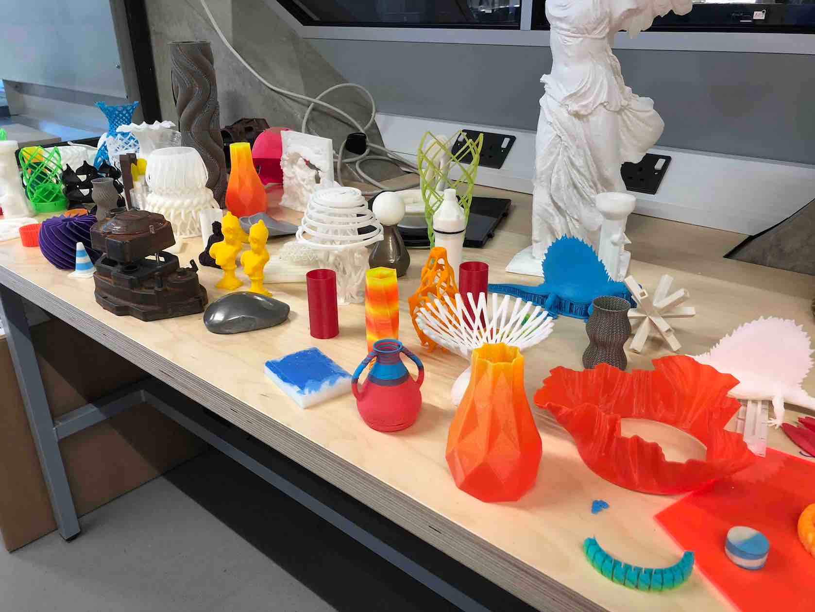
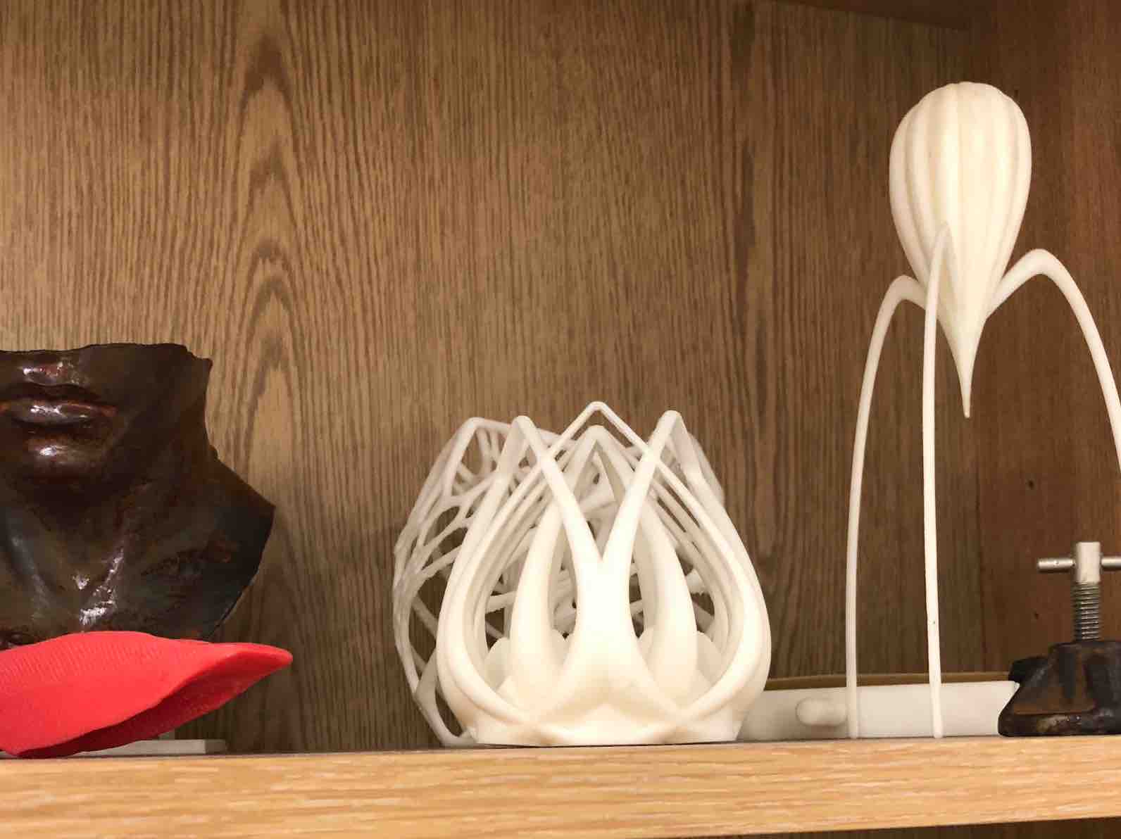
Because doing week 5 took forever to complete, I was behind on my 3D printing. It didn't help that initially I had no concrete idea of what to do as of course it had to also be something that could not be milled by a CNC machine and I didn't want to just make something random but something worthy of keeping or using later on. It took a while and lots of inspiration gathering but I got there in the end. I went with Kyle to the printer hub at the advanced engineering block at the Unversity and I took some sample pictures
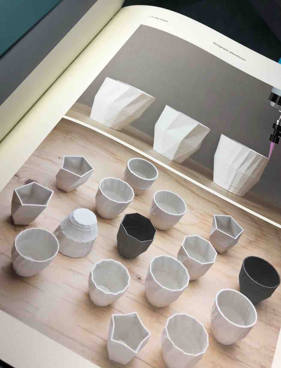
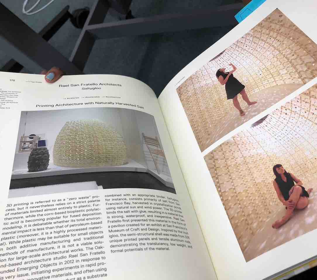
Earlier this week Luiz brought in a book that was filled with 3D printed ideas and it was going through it that I figured out what I wanted to do.
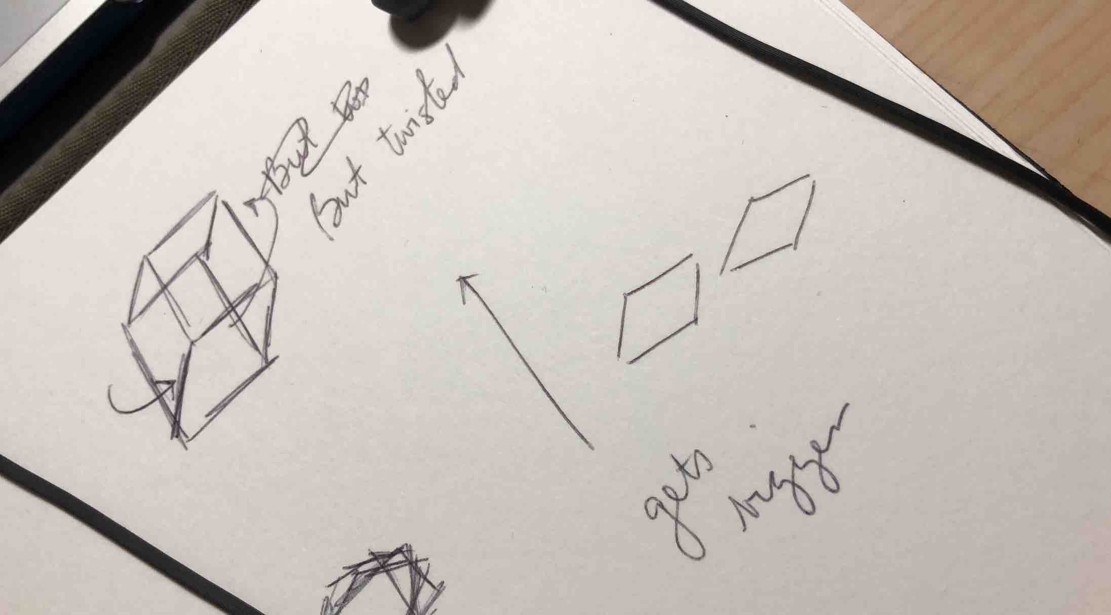
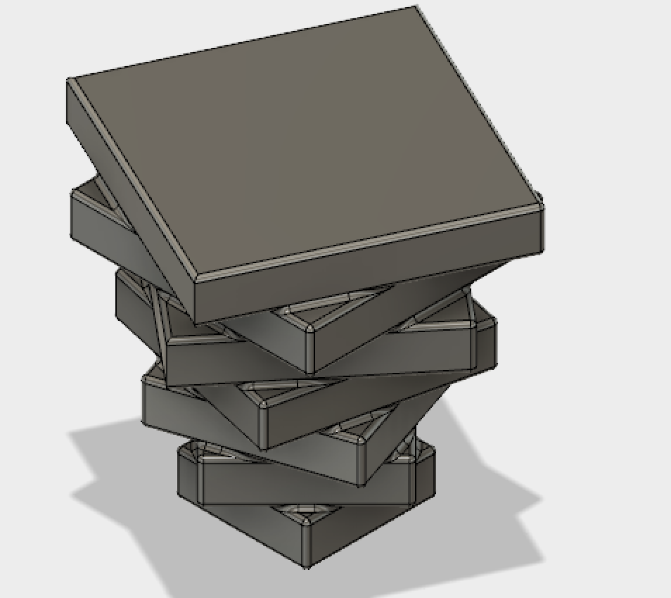
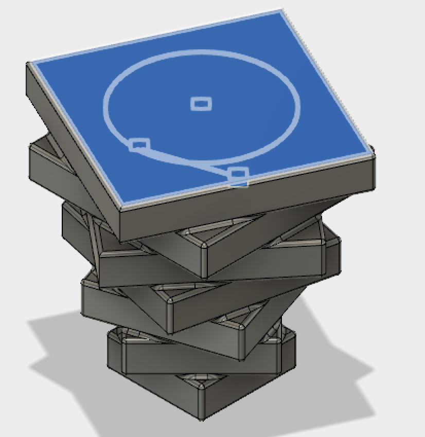
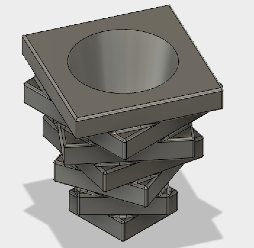
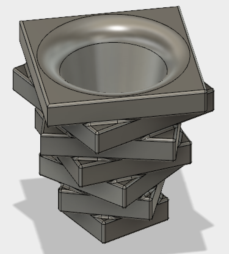
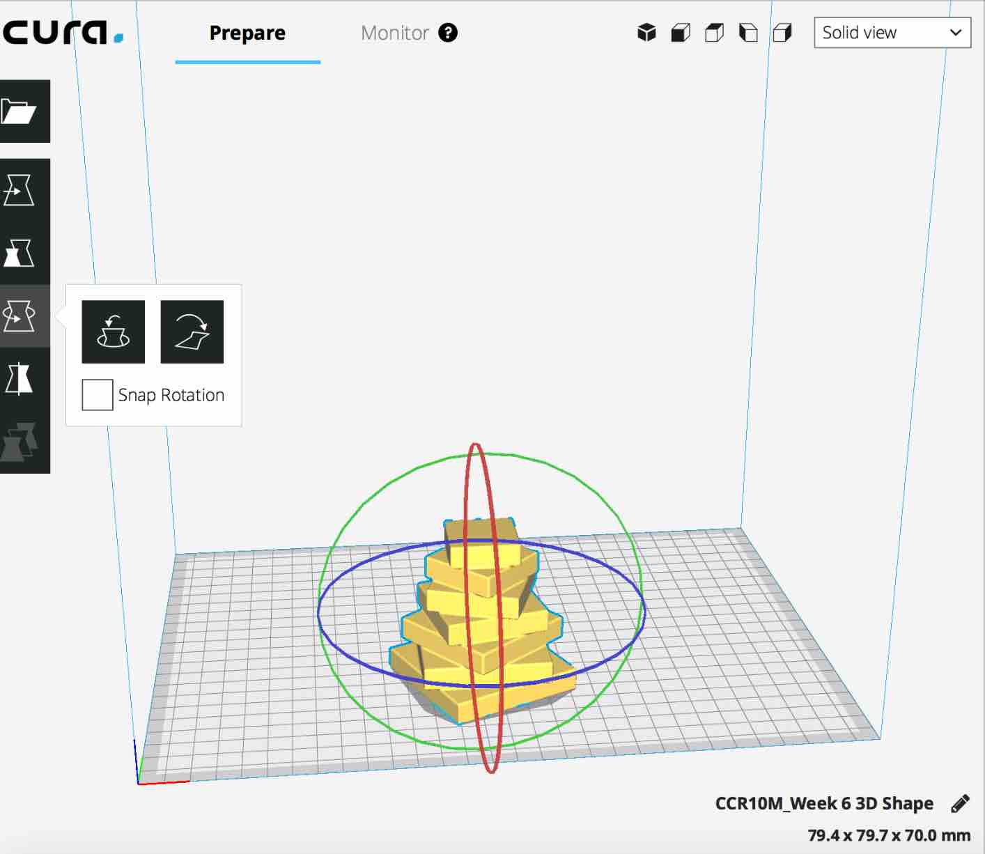
A cup inspired idea with boxes that rotate as they go updwards and increase in their size
I then managed to create it in Fusion and just need to print it out. As we are low on available printers I am currently just waiting for a chance to print. Luiz suggeste(upside down), so this is something I shall do to ensure it prints nicely.
take screenshots of fusion doc and how you made it!
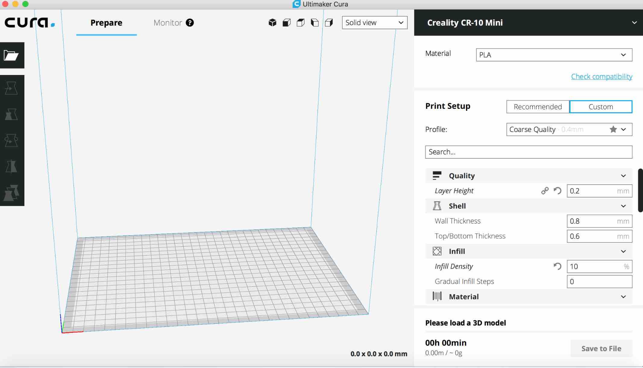
use screesnhots taken on curas
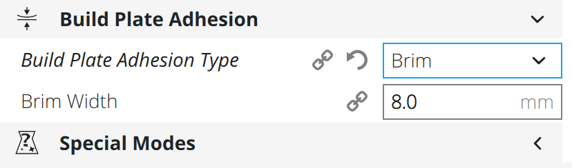
build plate adhesion - brim, was set to 8mm reason being so that you don't develop warp when printing.
"g" in .gcode stands for go.
Making the Shape on Fusion
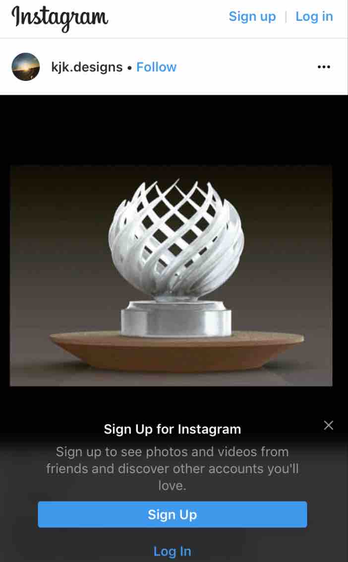
3D printing is new to me. Because of this, and the fact that I'm still learning how to maniuplate things to my likiking in Fusion I decided to first have a look at what can be or has been made, then draw simple inspiration from it.
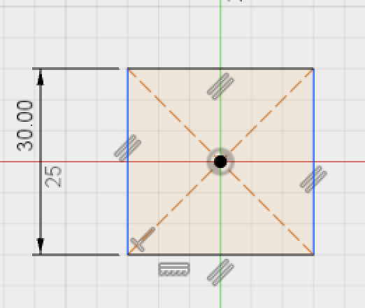
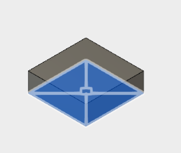
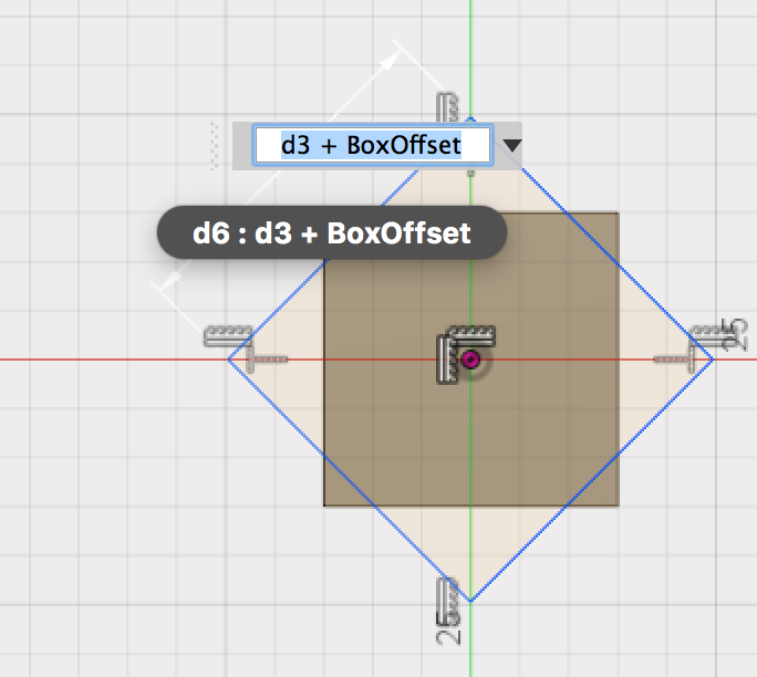
First I began by drawing a box in a new sketch and extruding it by 10mm. I added a parameter of 5mm so that I could just add on so that this way my box could consitently grow in area. This way I would just use the previous size and add on 5mm to it's area.
Using this box, I created another box ontop of the previous boxes face and extruded it, this time adding the 5mm BoxOffset, and again extruding by 10mm
I continued this pattern 7 more times. I decided 7 because I didn't want to make it too large especially since this was my first time so if things go wrong I'd be spemdig more time in the long run since it takes a while to print.
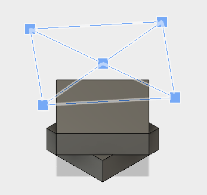
Then I used the fillet tool to round off the edges of the boxes. This was just so it would look cleaner (in my opinion) and be less "poky".
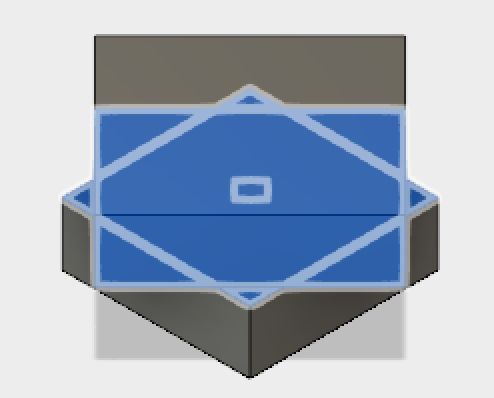
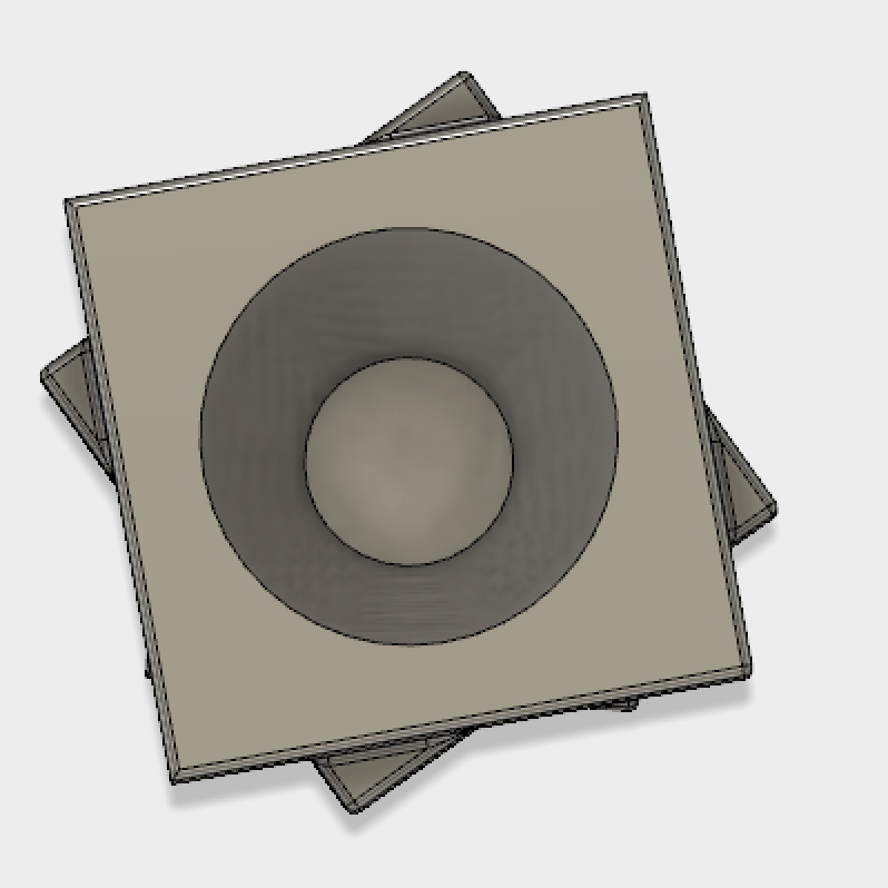
The next step was making the hole at the top of my shape (for the cup bit). I drew a circle on the top and then extruded it downwards. However, when ndoing so, I changed my angle of extrusion. This was for no other reason than getting creative and trying to learn new ways of doing things in Fusion.
After that, I also rounded off the top part of my circle again with the fillet tool just to keep some consistency going in my shape.
Scanning Shapes
For this I used the iPad Pro in corporation with the app "Scanner", found on the Apple app store. I also had download Autodesk's "Meshmixer" In the end I did prefer to use Vectary, an online 3D program.
Scanning though quite simple, to get it right takes time and precision because you want to ensure you scan as much detail and area as possible. I attempted 3 different objeccts to scan, of which only 2 manged to work. The other did not work because it was a combination of items together and I used tinfoil crunched up at the base to make the object stand. However the scanner did not seem to like the tin foils' presence. The other two objects were a drill and a 3D printed object.
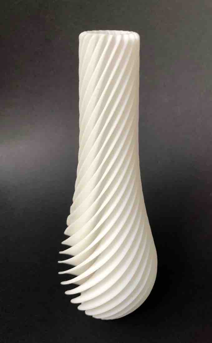
The 3D object
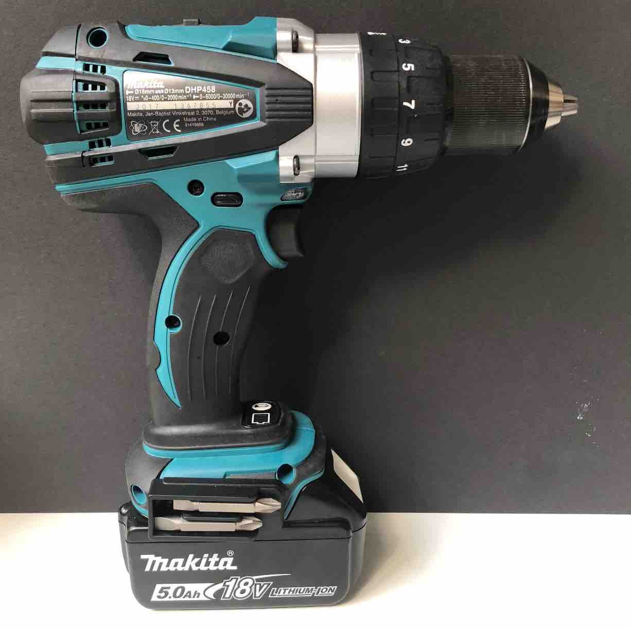
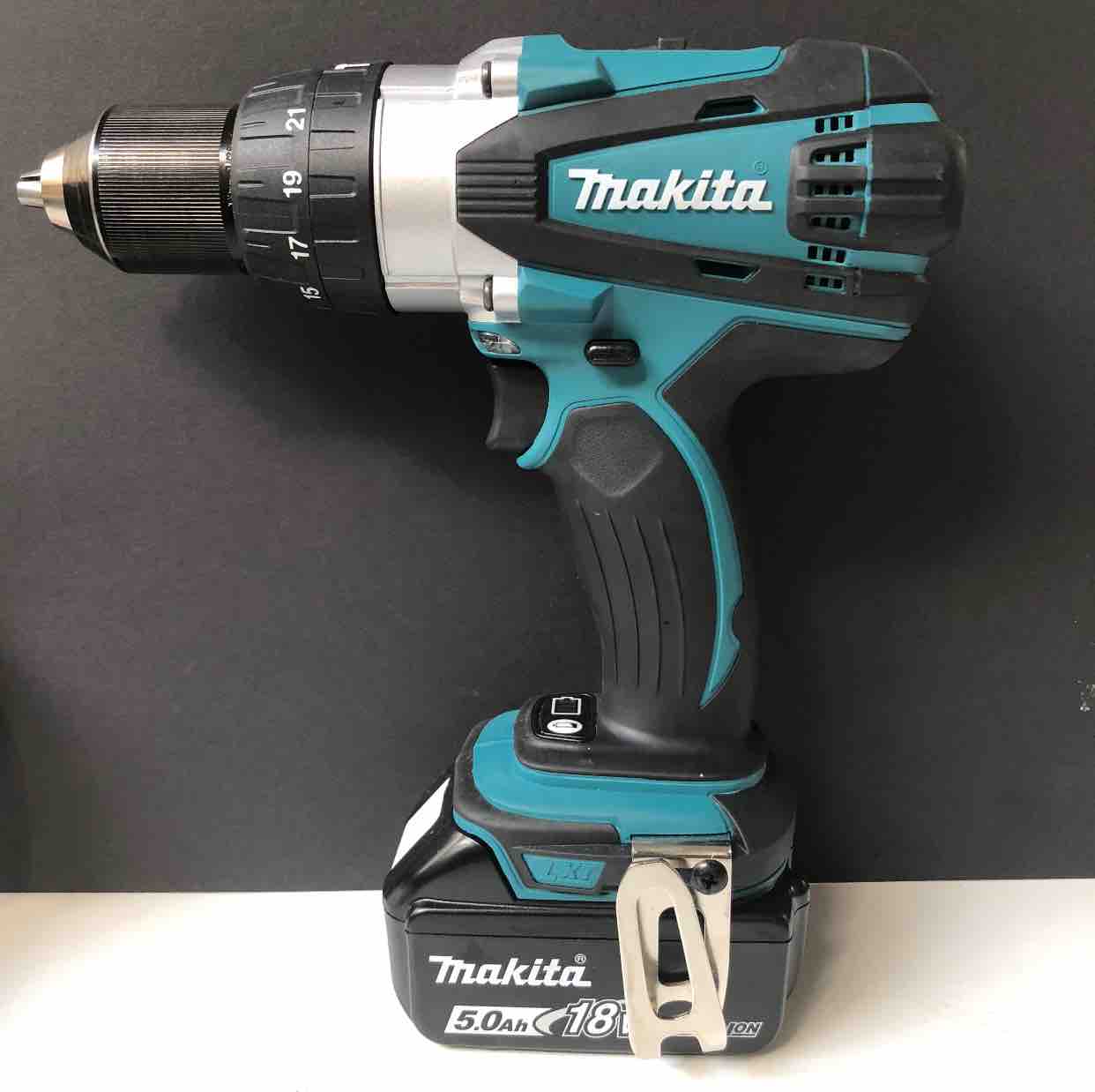
The drill
When scanning the 3D printed object, because it is a relatively simple looking shape it was easier to scan than the Drill. However, the details of the 3D shape did not scan well.
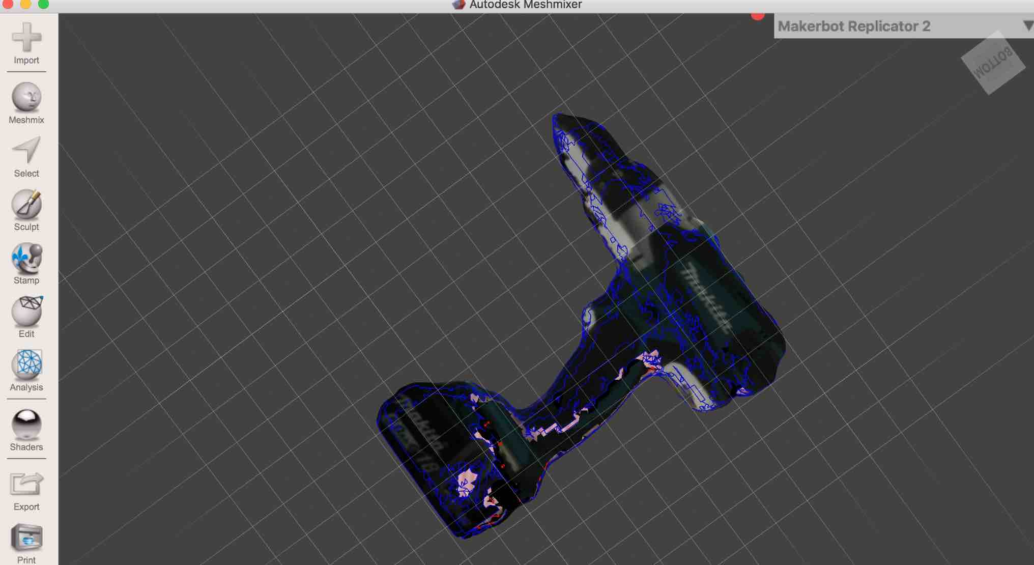
As for the drill, this one took more time and patience to scan because of all the intricisies. One area that was hard to capture was the hook area of the drill. I only just about managed to get a good majority of it scanned. Unfortunetly, what I had forgotten to account for was the under side of the drill. As a result, the scan came out with a hole in it.
To solve this I attempted two methods on two different softwares, one turning out to be better than the other. One was Autodesk's Meshmixer, the other an online one called Vectary.
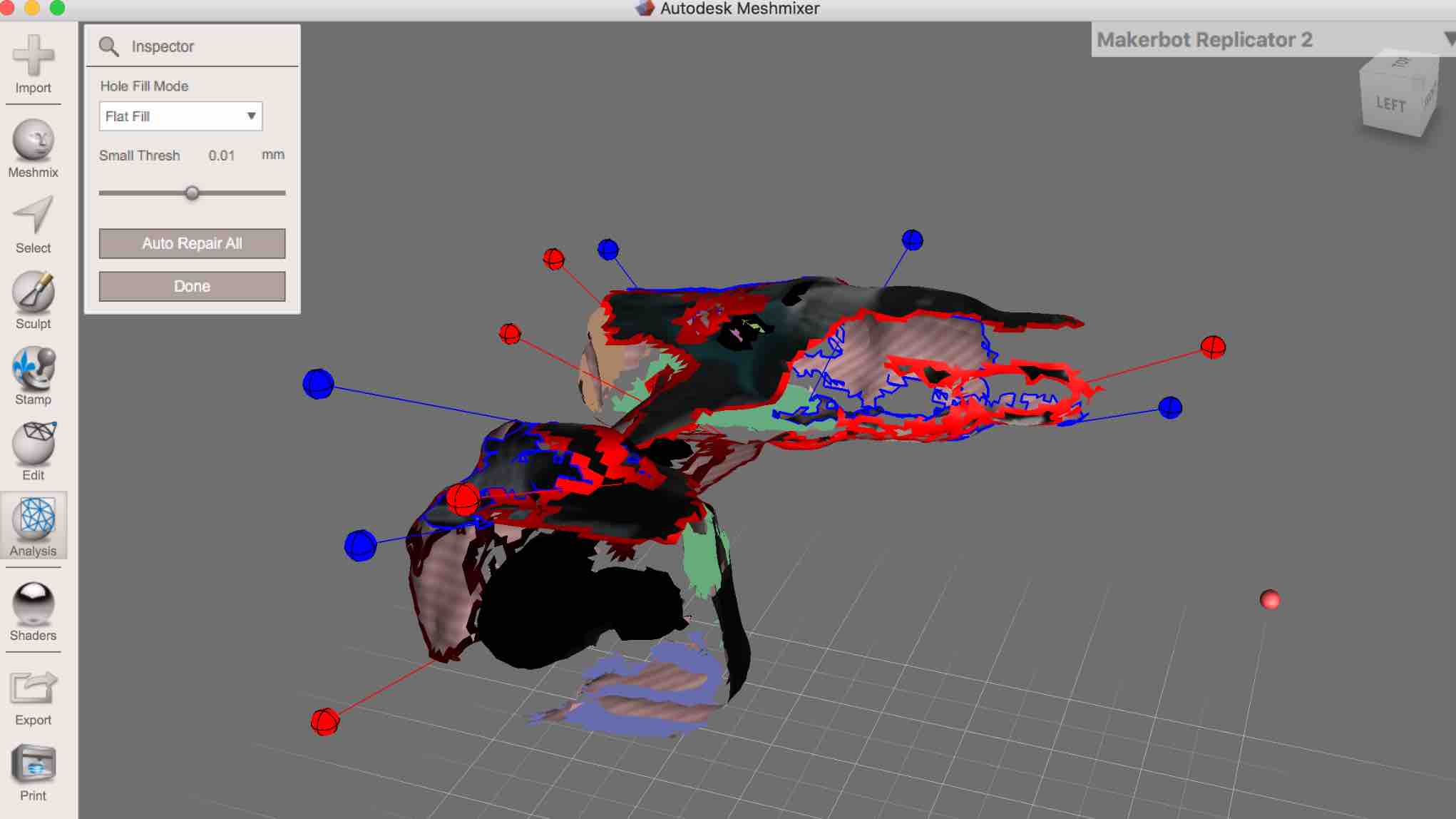
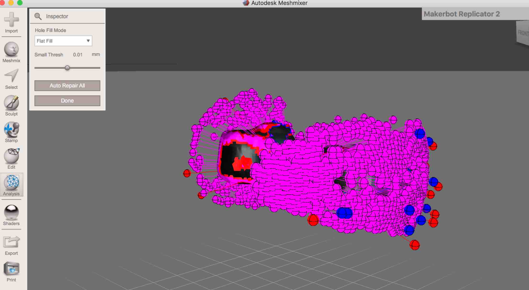
My issue in Meshmixer, was that their offered solution to patching up or "filling" in holes did not work well for me. I am not sure if it is because I perhaps do not quite understand how to use it or if it is because the hole was too big or abstract to work, but it did not work. I tried to both select points and to "autofill", the selection of points ended up weirdly enough removing parts in the scanned object, whereas the fill would completley change the piece (check out image below).
This was the result of using the "Auto Repair" "Flat Fill"
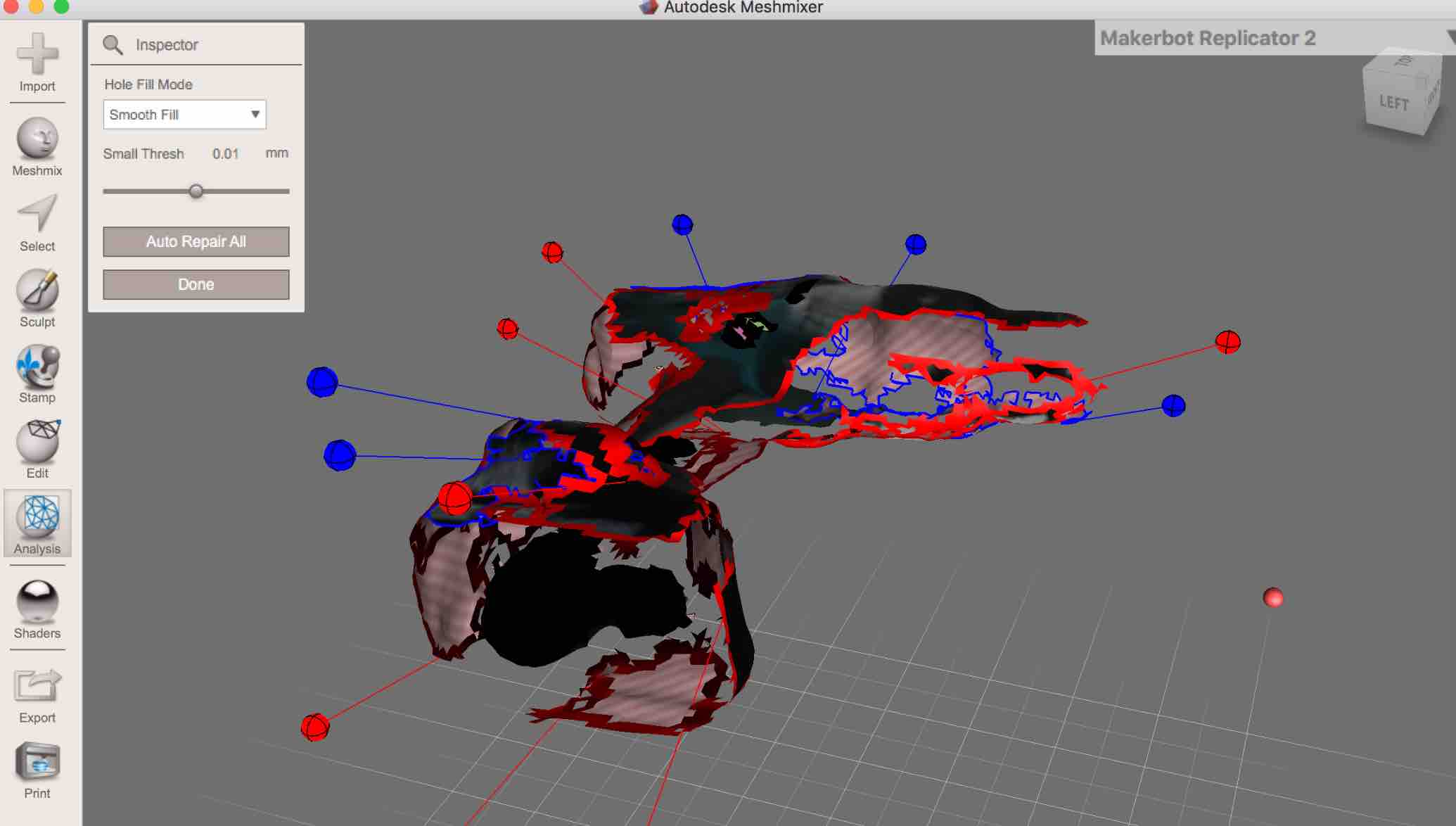
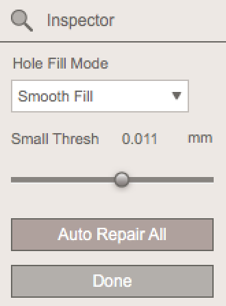
This was the result of using the "Auto Repair" "Smooth Fill"
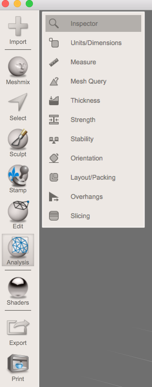
In order to get here, you need to select "Analysis" in the side panel and then "Inspector". This was not very clear to me the first time I attempted to locate it. Which is why I've made a screenshot now that I do knonw where it is. Took ofrever to find. Funny thing is, it's blatently obvious. But only if you know where to look. I suppose that applies to anything and everything in life however.
Reference images to ensure you're looking at the right thing...
I used these links to help me figure out how to do what I needed done. I initially just typed into Google search "meshmixer filling holes" and well then after getting some terms in like auto repair, adjusted my search terms.
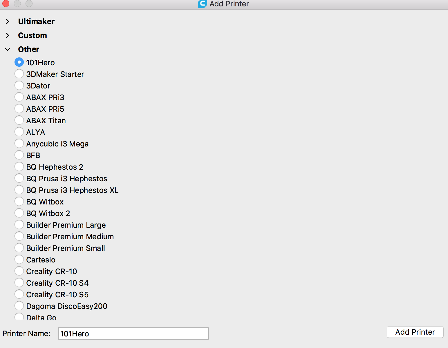
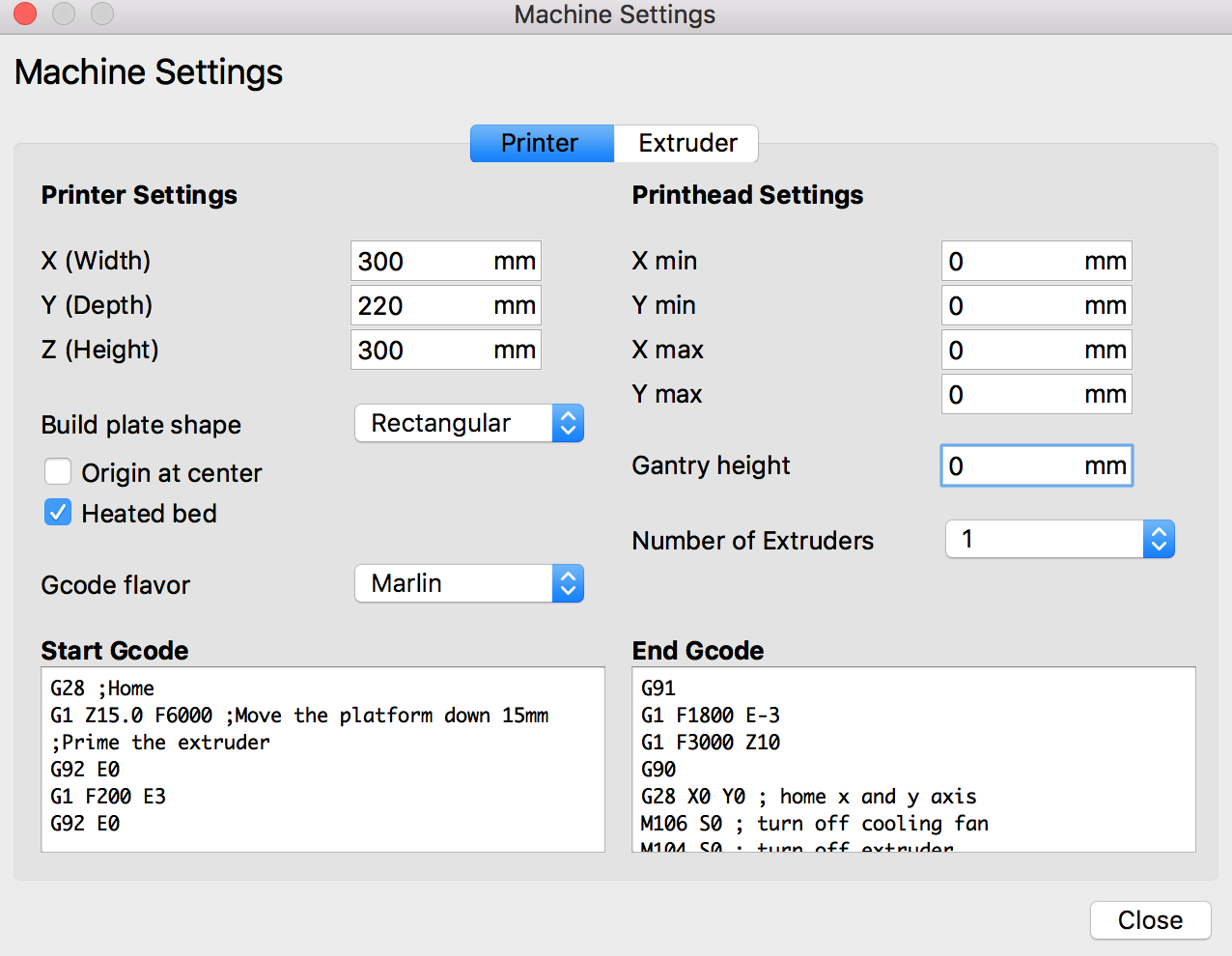
"Machine Settings: Where youput printers sizes - size of the bed
"Printhead": If there is an offset, you can put it in here
"Heated Bed": Plate will be heated, tis means that the m aterial can attach better to the surface of the bed
"Origin at Center": Do not have this sticked (it will use the origin of your drawing)
"gcode Flavour":Selectin Marlinn - this is the firmware
"Number of extruders": Write 1 (in my case we only had one)
"Start gcode":This runs through the whole code before it prints anything
"End Code" This happens at the end no matter what the slice command is
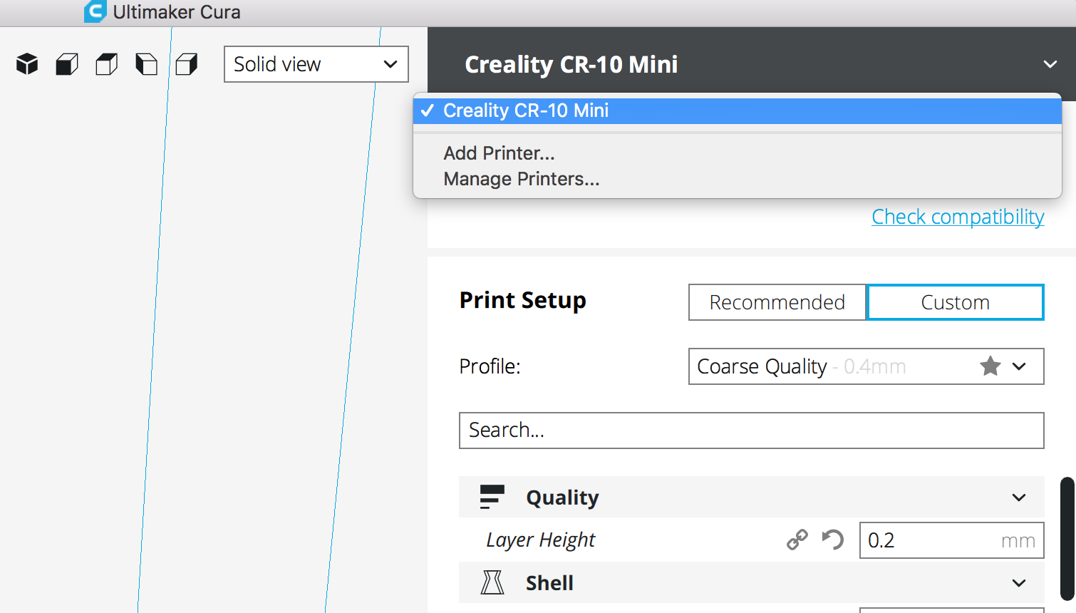
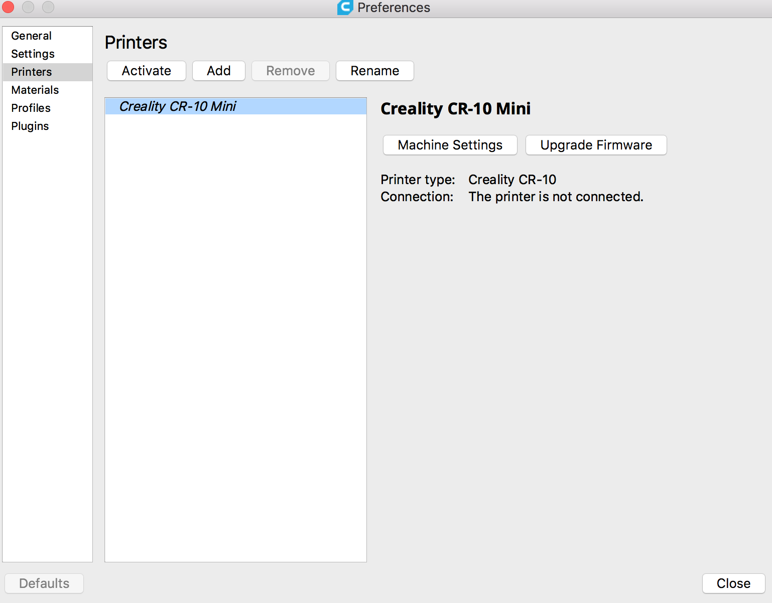
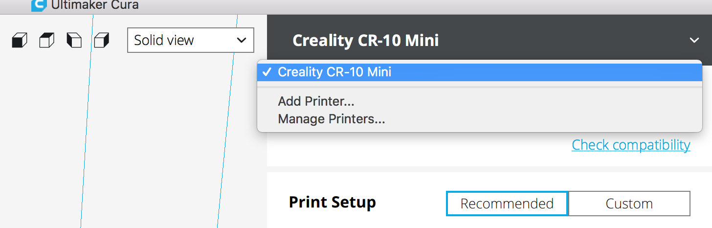
If you wish to change something at this point or later regarding your printer, you can go to "Manage Printers"
Use the transformation tools on the left side of the screen.
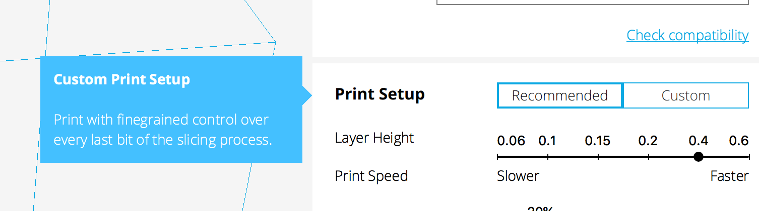
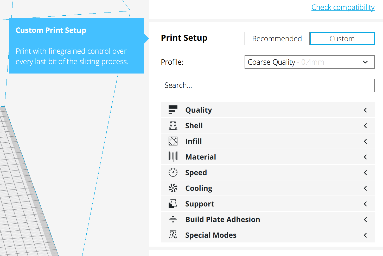
Under "Print Setup", you can choose between recommended (good for beginners) and custom (allows for more flexibility)
"Quality": Layer height. You can use 0.2mm or 0.1mm.
0.1mm - This is slower, however it produces maximum quality
0.2mm - This is faster that the 0.1mm choice, however the quality is less and can be a bit rough. It normally is a bit stronger
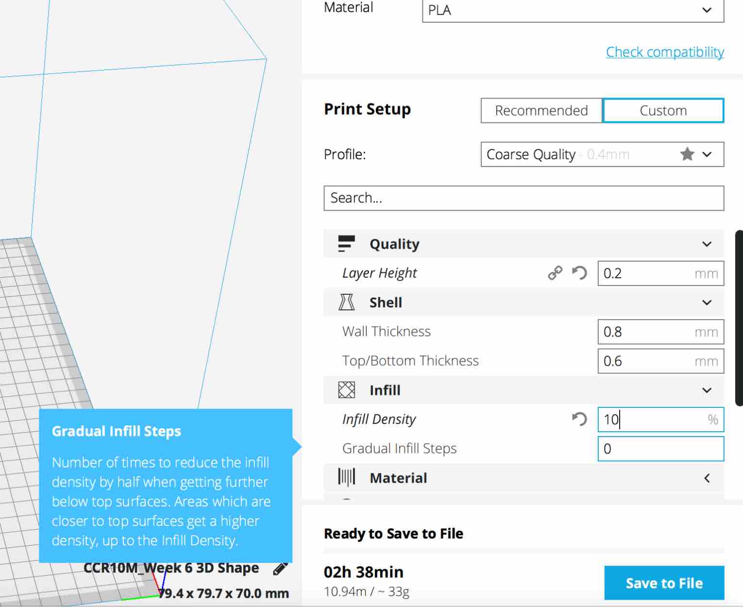
"Infill": Set this to 10%. The reasoning for this is that it is strong enough to keep the structure corrrect, whilst still saving on printing time. 20% Would be much stronger.
Note:
0% is no fill
100% is all fill
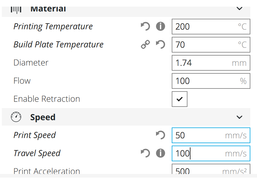
"Material": For this, you can collect most of your information from the material's packaging. I got my data from it:
"Printing Temperature": 200 degrees celcius
"Build Plate Temperature": 70 degrees celcius
"Diamter": 1.74mm
"Flow": 100%
"Enable Retraction": This should be checked. What this does is is everytime the extruder head moves, the fillament is sucked back in a little bit. This is to prevent fillament all over the shape in the end.
"Speed":
"Print Speed": 50 mm/s
"Travel Speed": 100mm/s
"Cooling": Make sure this is enabled. This will make sure that per layer, the fan helps cool the shape
"Build Plate Adhesion Type": Set...
"Build Plate Adhesion Type": to Brim
"Brim Width": 8.0mm
You will see that at the bottom right it will show you how long the printing process will take. This is updated live as you adjust settings
Click "Save to File" - this will generate and save a gcode
Build Plate Adhesion Types and Their Functions
Brim - The printer prints a brim around the piece before actually making the piece. It draws a shape around the piece then, still touching, goes on to print the piece. You then break this extra piece off when you're finished printing.
Skirt - Similar to the brim option, but instead of touching the piece when it goes on to actually print the piece, it does not touch. Instead, it gets very close to the shape, then lifts up and shifts over to start printing the piece. The shape is then left on the surface of the printer afterwards.
Raft - Raft is similar to the Brim, except the shape printed surrounding the piece is much thicker and more stable. It is thicker and therefore better for adhesion)
Advantages of 3D over CNC Milling
When using a CNC milling machine to create shapes, your dril bit is your limit. This means that certain shapes/corners/edges cannot be achieved
3D printing allows for layer by layer printing - additive process - something a CNC milling machine cannot do. For example, if one wanted to create a shape that looks like the image below, it would not be possible using a CNC milling machine since once the materical has been cut, it's gone and can not be retried. This doesn't apply to a 3D printing though.