Andrew Sleigh and Paul Nicolas and myself, together we make the three Polarteers. We all agreed upon doing a Polargraphy. I personally wanted to make one, at the time, because I wanted to incorporate cogs and a sort of pulley like system to my final project (though my final project has altered since).
My role in the team was to...
spalling - what you get when two same materials rub against each other and over time ware eachother out.
As I did not manage to finish with my group due to my university degree exams, I had to create my own machine.
I was inspired by my instructor who created something quite unique...see for yourselves:
It reminded me of one of my ideas for my final project that I came up with during my first week at fab academy, but a smaller scaled one.I thought I would go try to make something similar but with two pens instead.
My initial idea was to create one with lots of pens to create a rainbow. Unfortunetly my ideas did not match my wallet and what was available to me so I had to downsize my idea.
This was a huge issue for me. I had returned to the lab in Brighton from Germany and had very little time to get everything done, including projects that weren't this week's focus. It meant that any big scale ideas I had, I had to downsize them and keep them as time realistic as possible.
I made the mistake of not having settled on an idea sooner, and so by the time I did, I had no time to go get the equipment I required. For example I needed 2 servo motors. Unfortunetly I only had one and that one belonged to my friend Kyle as we did not have any left in the lab. Another was the soft potentiometer. However that ended up not being much of an issue anyways because after programming one to work, I quickly discovered I did not like it at all as when you are not touching it, the servo makes minature movements. I did attempt to control it (see code in week 15), but it did not work out too well.
So it was then that I decided to move onto potentiometers. Luckily for me however, there were some that some of the guys had scavenged from the music department, which had some. So I desoldered them off of the boards to use for my project.
In this video, Michael helps demonstrates to me and whoever is watching how to desolder a potentiometer. We had scavanged some music stuff and this was on one of them. Yay for recyling! THAT IS THE FAB LAB WAY! :)
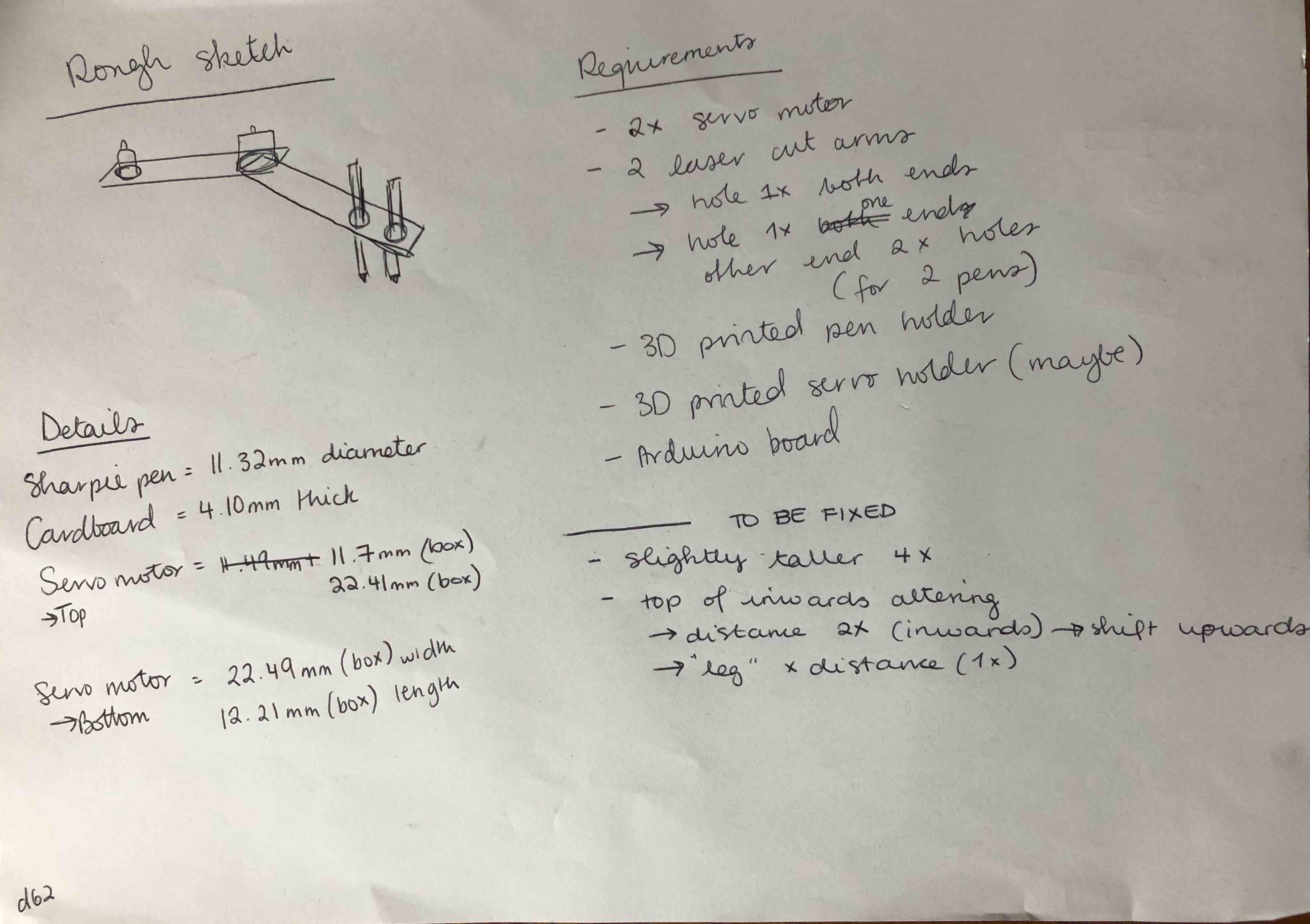
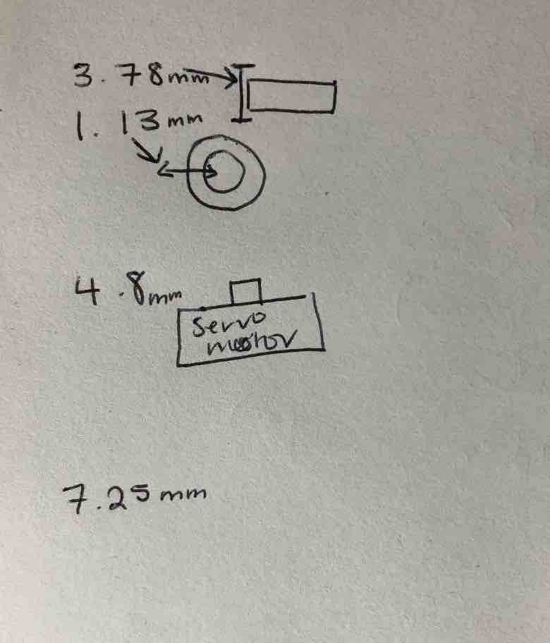
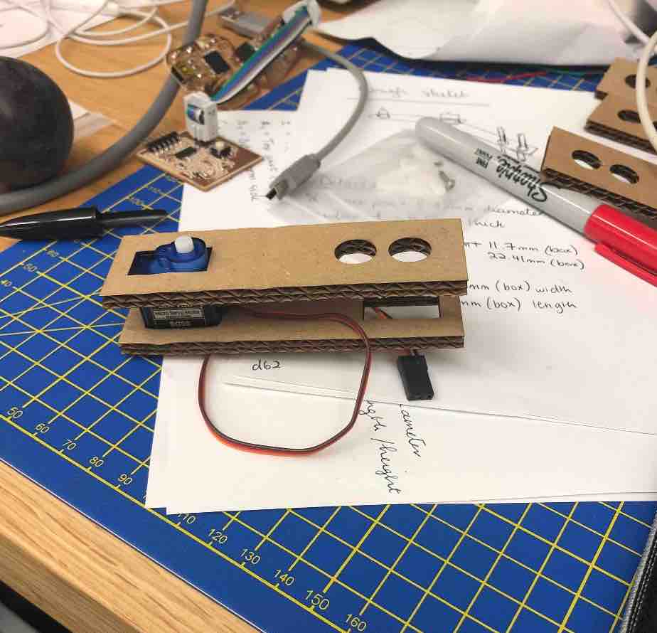
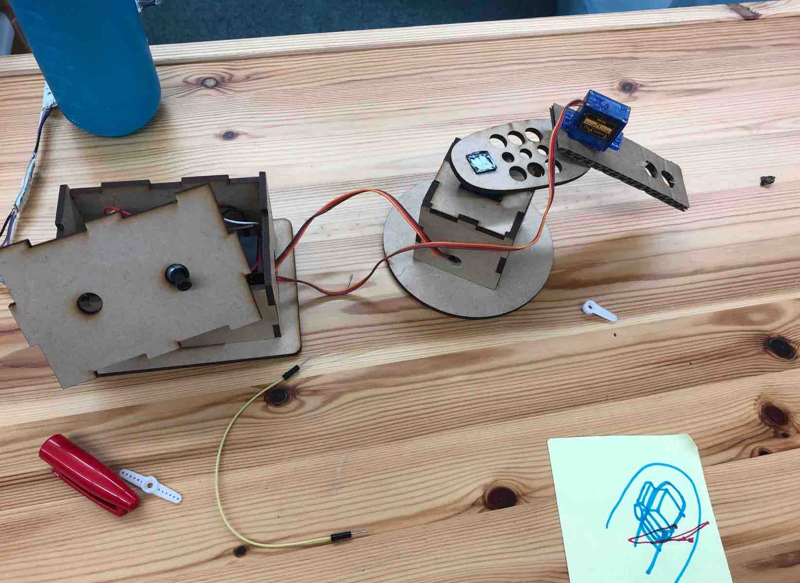
The first step was to get my materials together and start measuring. I measured almost everything, from the size of the sharpie pens (I needed to know how big to make my cardboard holes), to the size of the potentiometer and the carboard itself. This all came in handy later, especially when making the servo head.
After noting them all down I took to fusion to first get the arms. Initially I was to use MDF, but after speaking to Kyle, we realized that his servo motor would most likely be incapable of holding it all up. So I figured, what would be sturdy, but super light? CARBOARD! Also super easy to cut I might add. And once I am done, if I do not wise to hold onto my minature machine, I could throw the carboard away and it would be recylced! :) everyone wins.
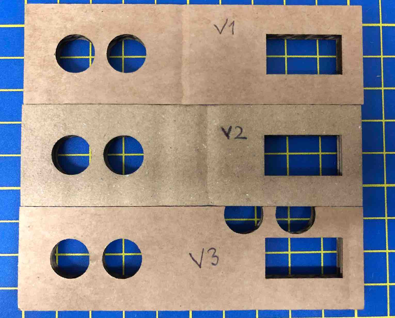
I went ahead and kept laser cutting and testing and going back to laser cutting....
...until I came up with a size that I was happy with.
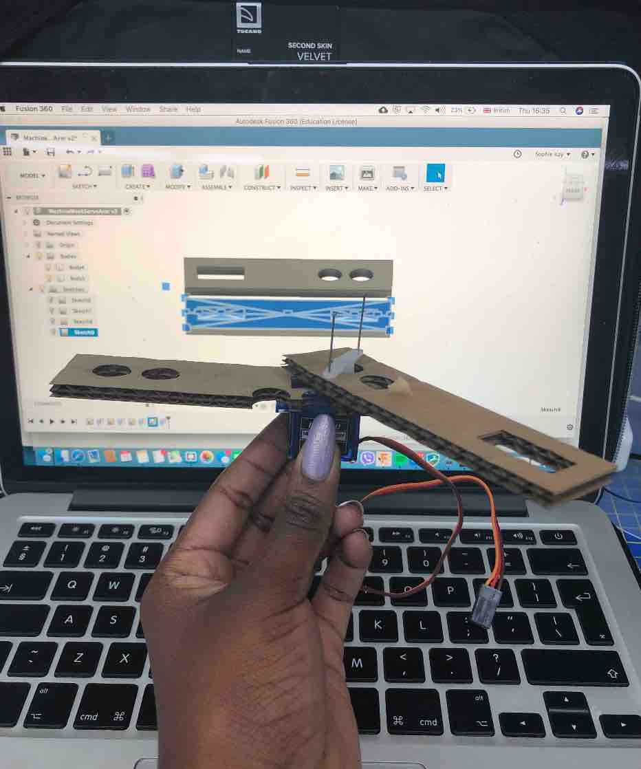
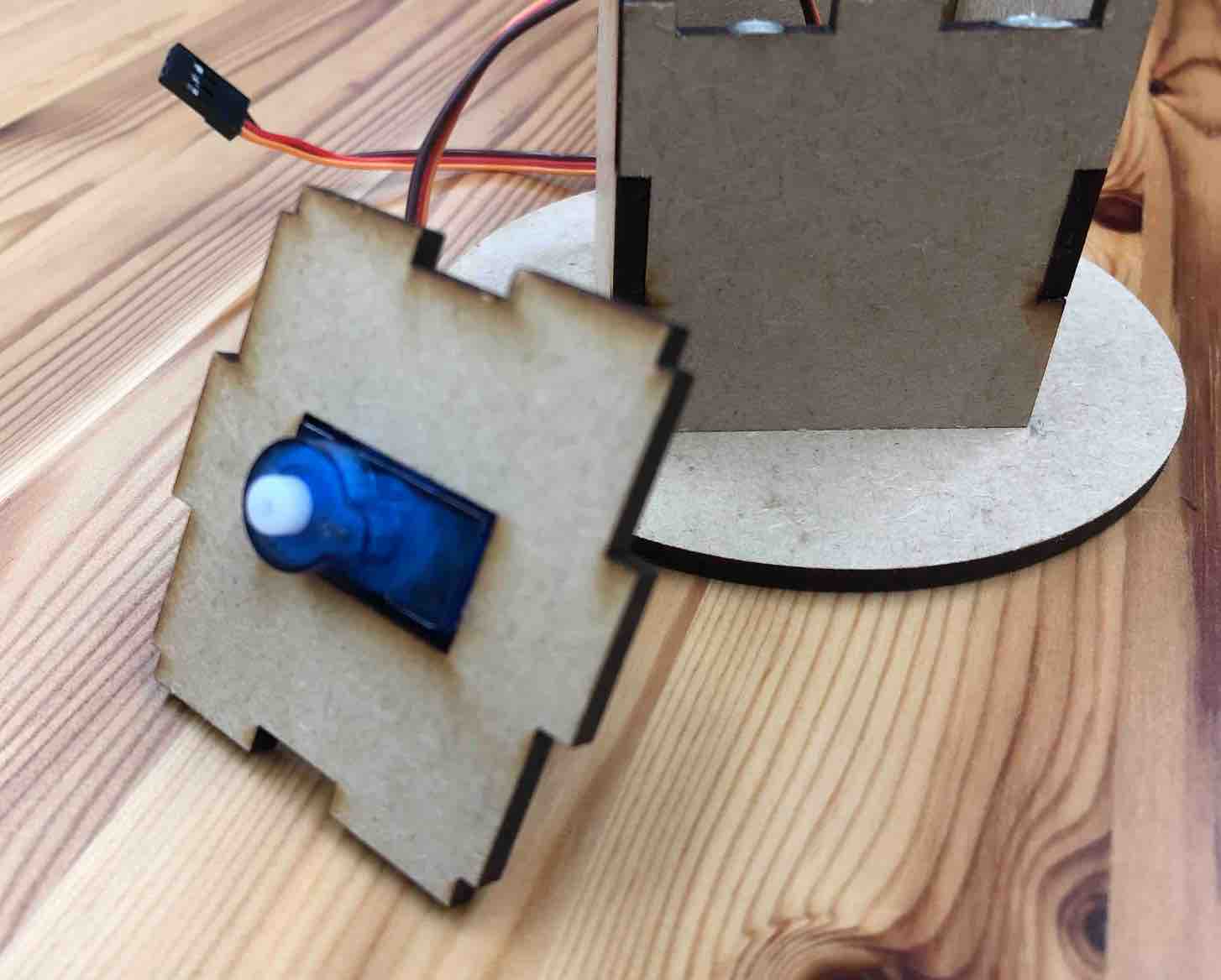
The next step was to fit it all together to see what was the best way to get the servo on there as well. This was a bit of a challenge because of the wires at the bottom, and the lack of a tall neck at the top. I also had issues because I was unsure of how to laser cut the sort of top heavy bottom light 8 shape the servo head had. I was hoping to create a pole using 3D printing to elongate the space, but I simply could not figure out how to measure the hole on the attachment end and the servo end, and then the rivets too. But I soon realized by placing my servo in the same space as the sharpie that I could just change the shape to a circle and place it on that way.
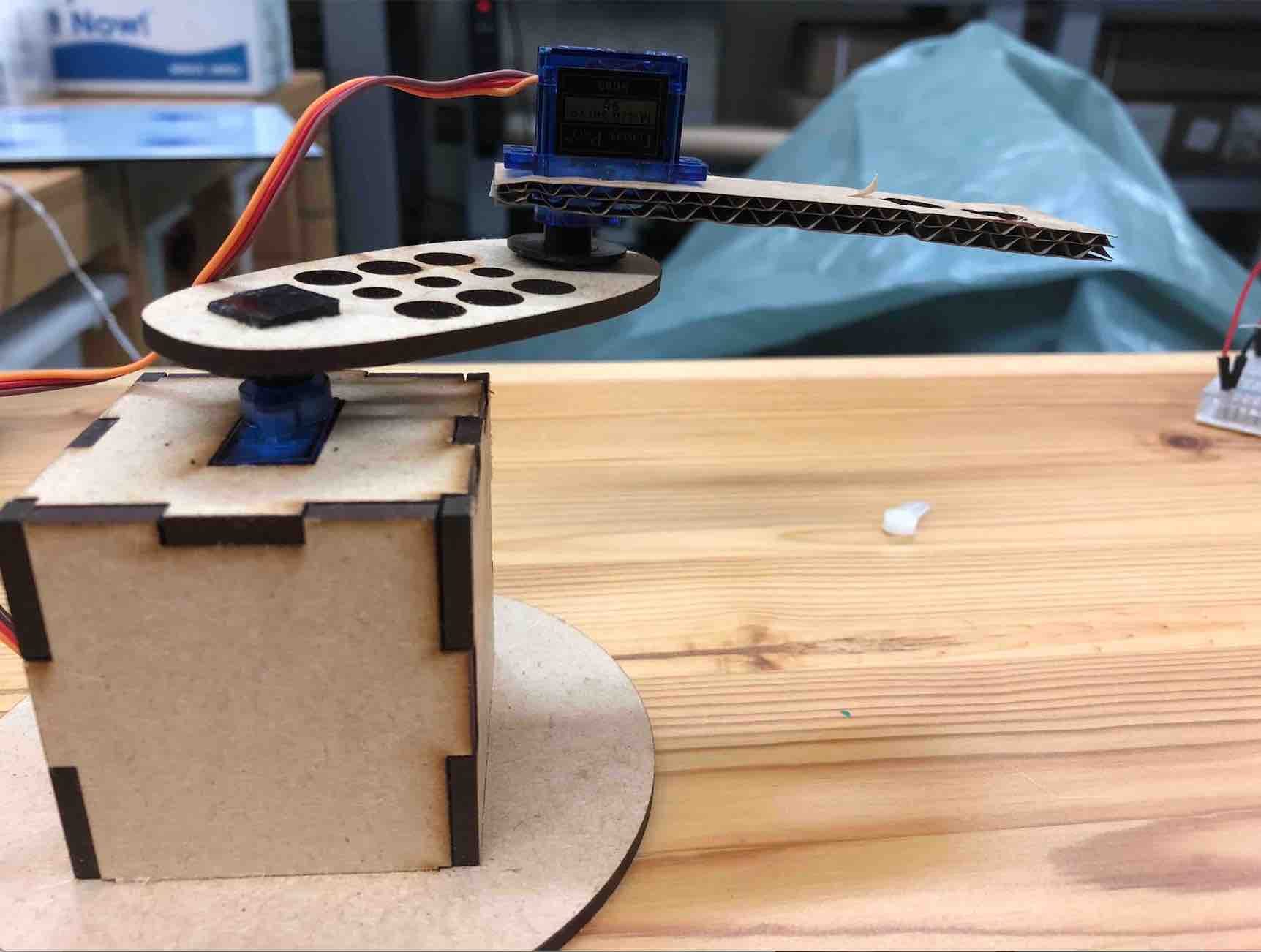
I tested the movement capability by moving the servo around too physically and it worked.
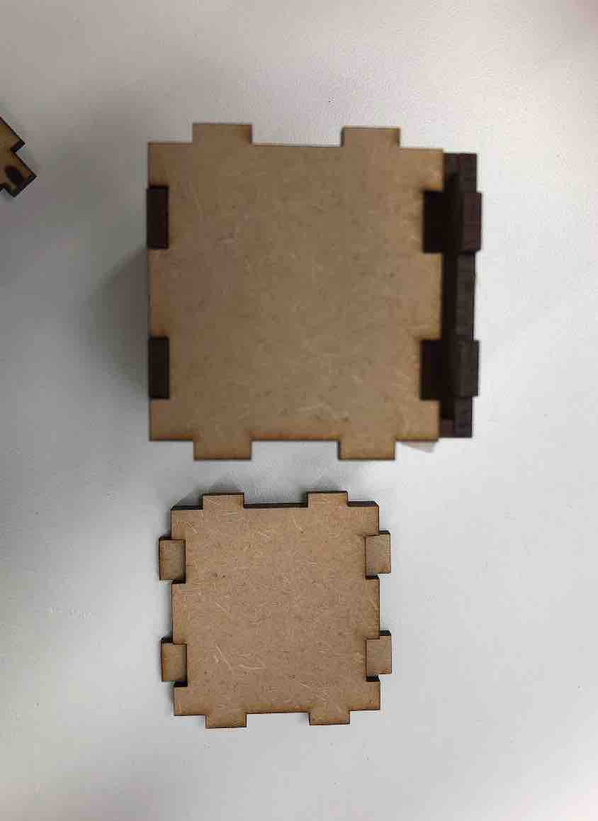
The next thing on my plate was to figure out how to get the servo to stand "in the air" as I didn't want to hold it as it painted. The answer of course in the sentence; create a stand!
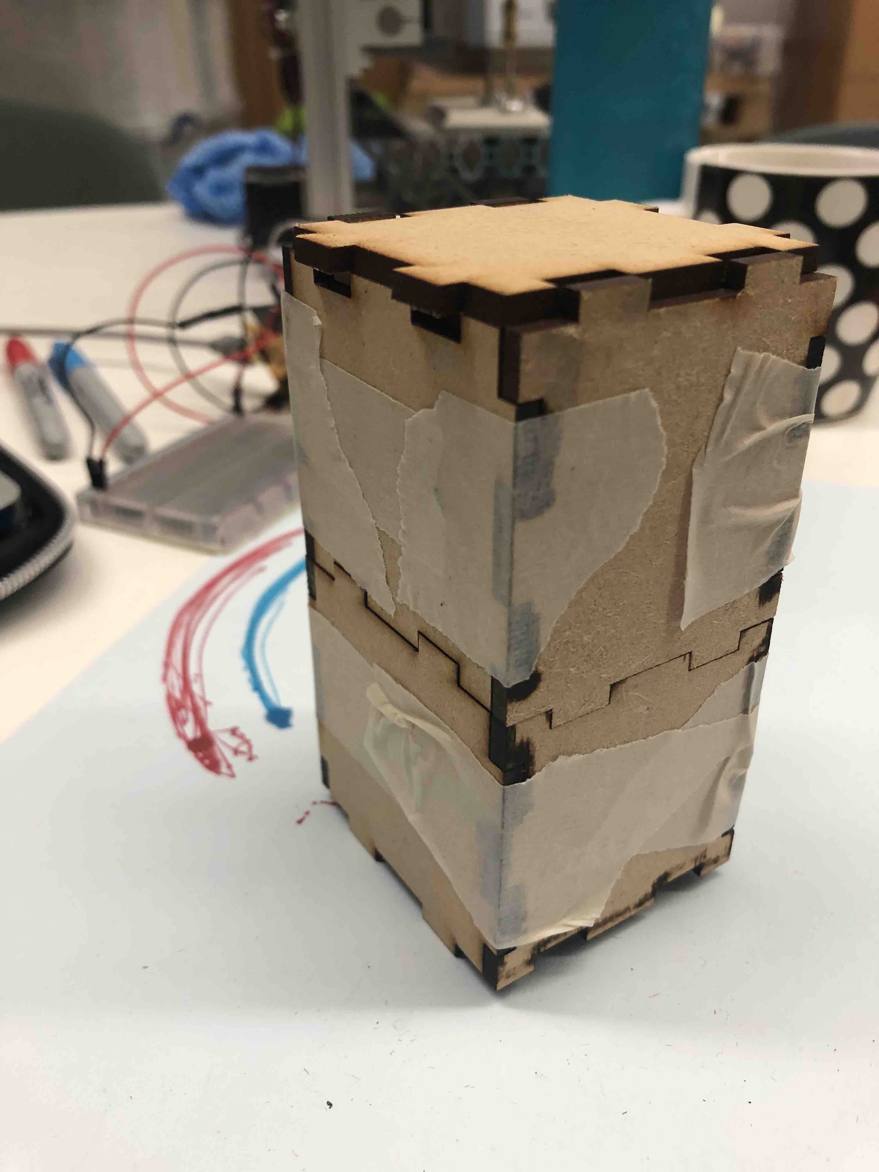
Easier said than done. I came up with lots of varying box shapes, and yet I could not get the top part to fit. It was always off, just slightly. Very frustrating.
I had a mini problem trying to figure out how to rid the sides in illustrator but Michael showed me the way!
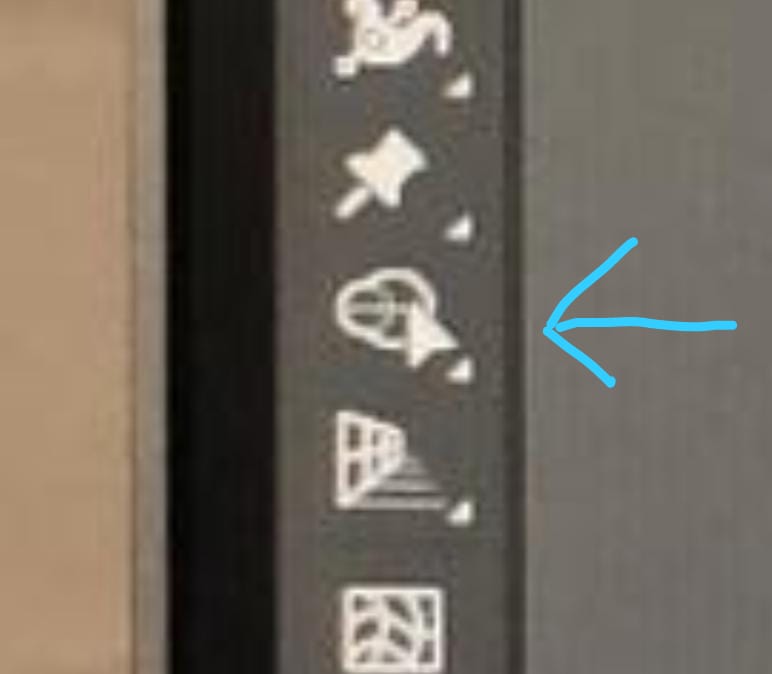
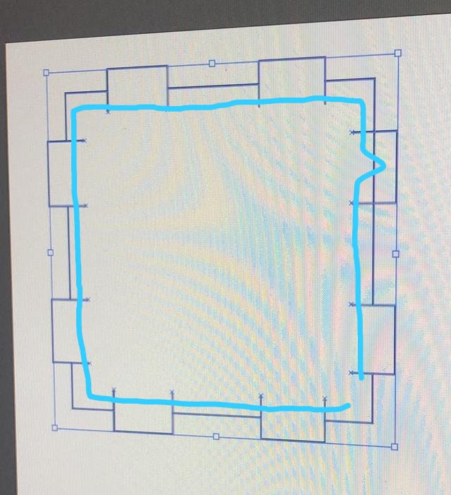
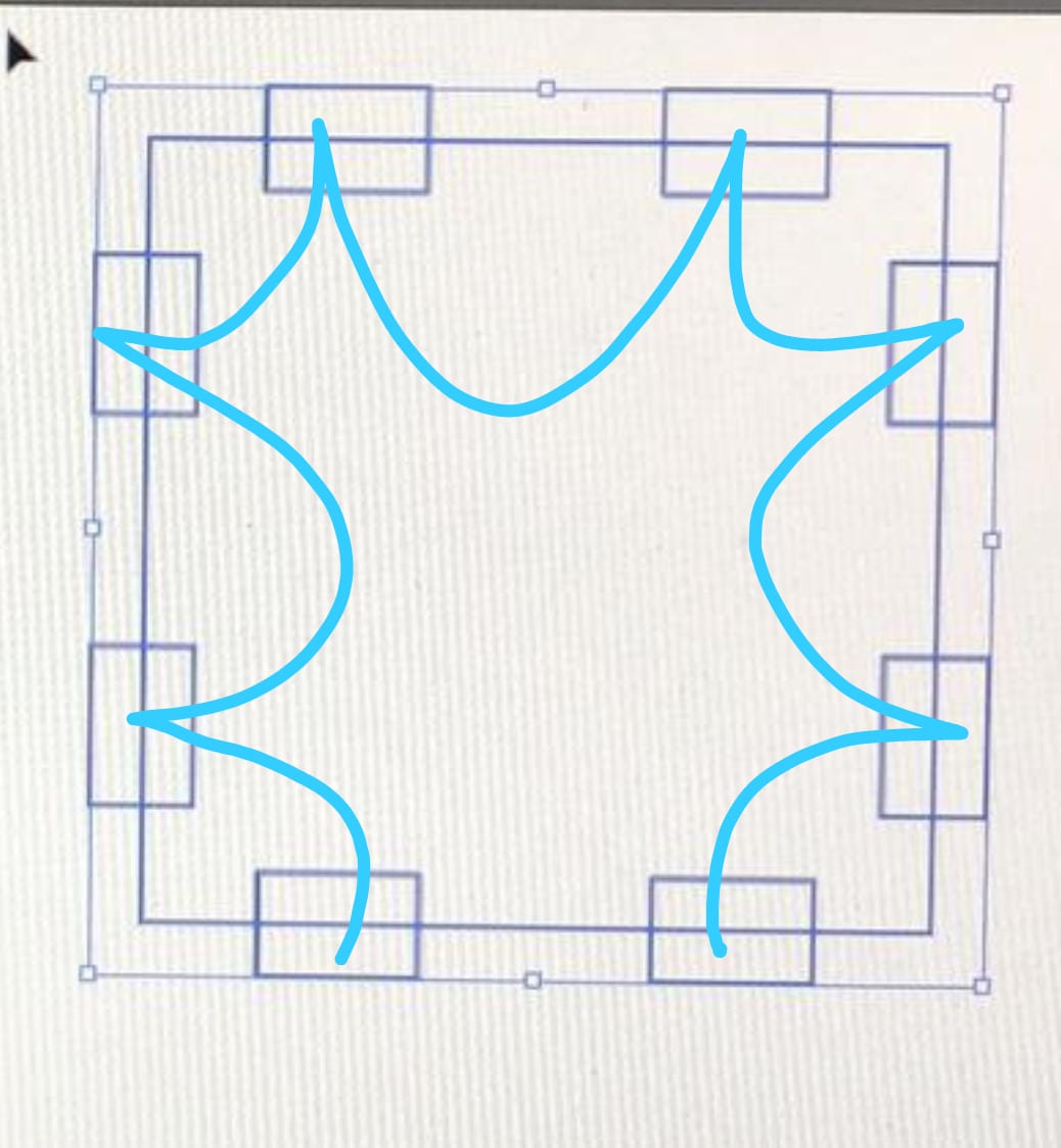
Essentially you select the part, then using the tool in thr left hand panel as shown in the first image, you select the parts you don't want then hit delete. And continue to do so till everything you want gone is gone like in the second and third image
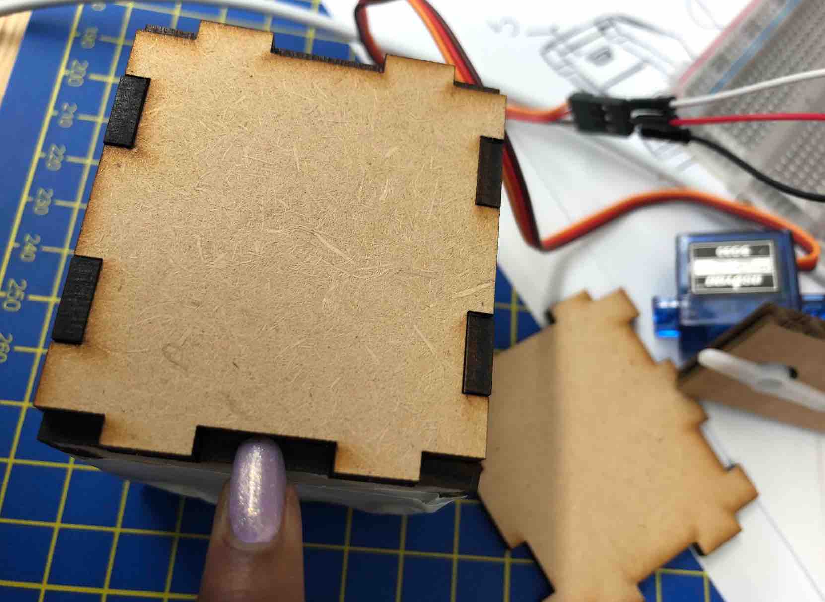
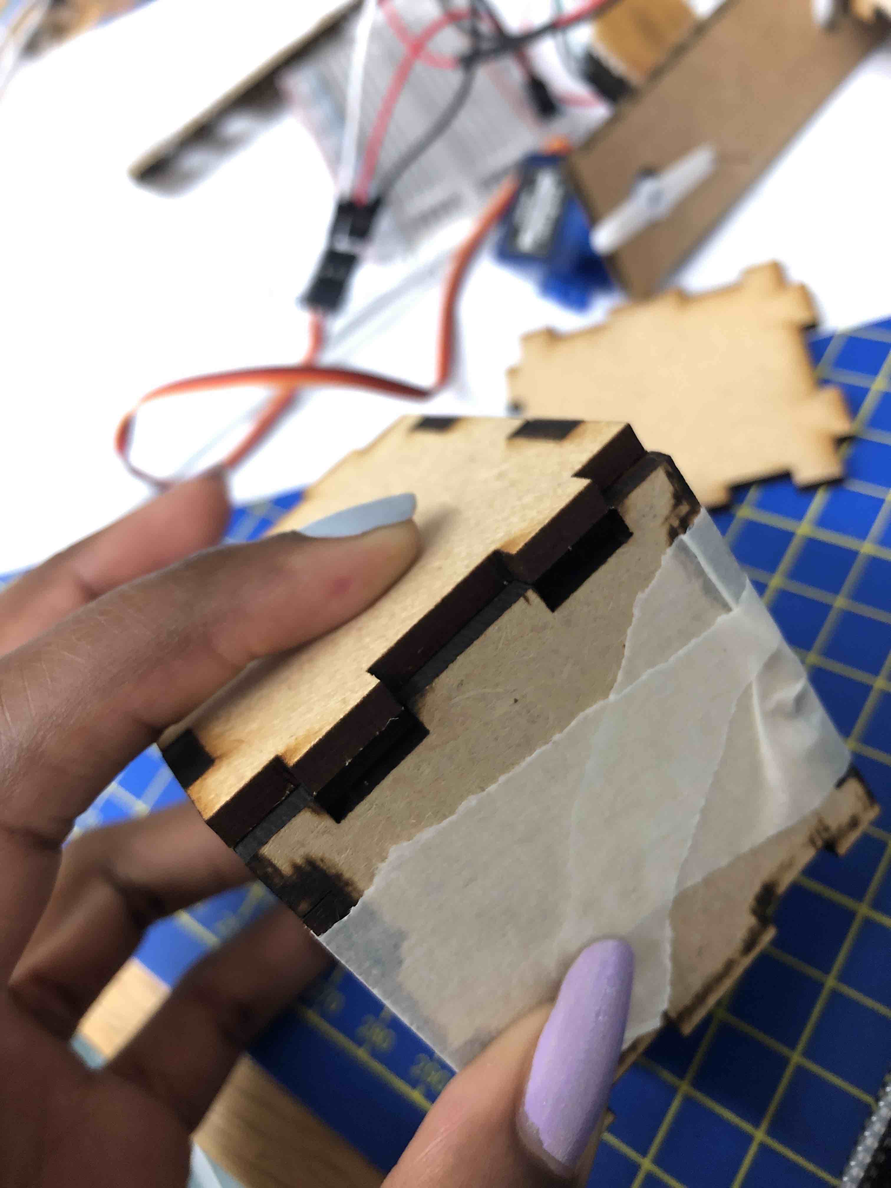
In the end though, my buddy Michael assisted me with my stand problems. We came up with a stand design that worked very well!
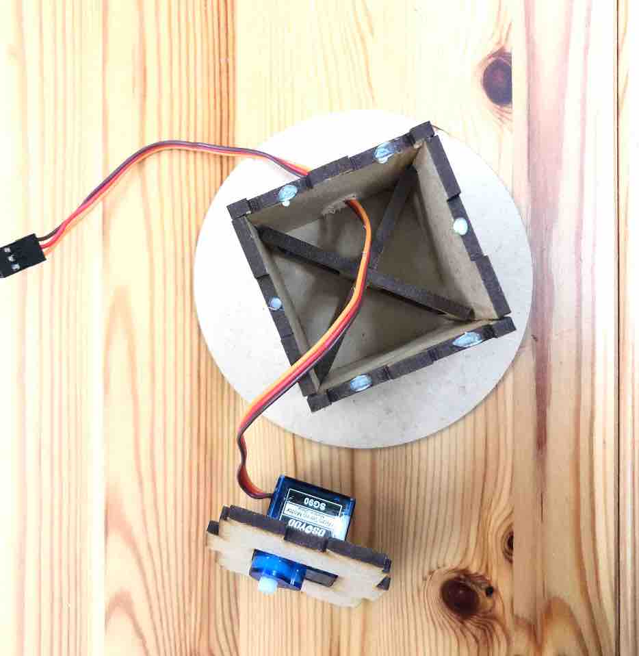
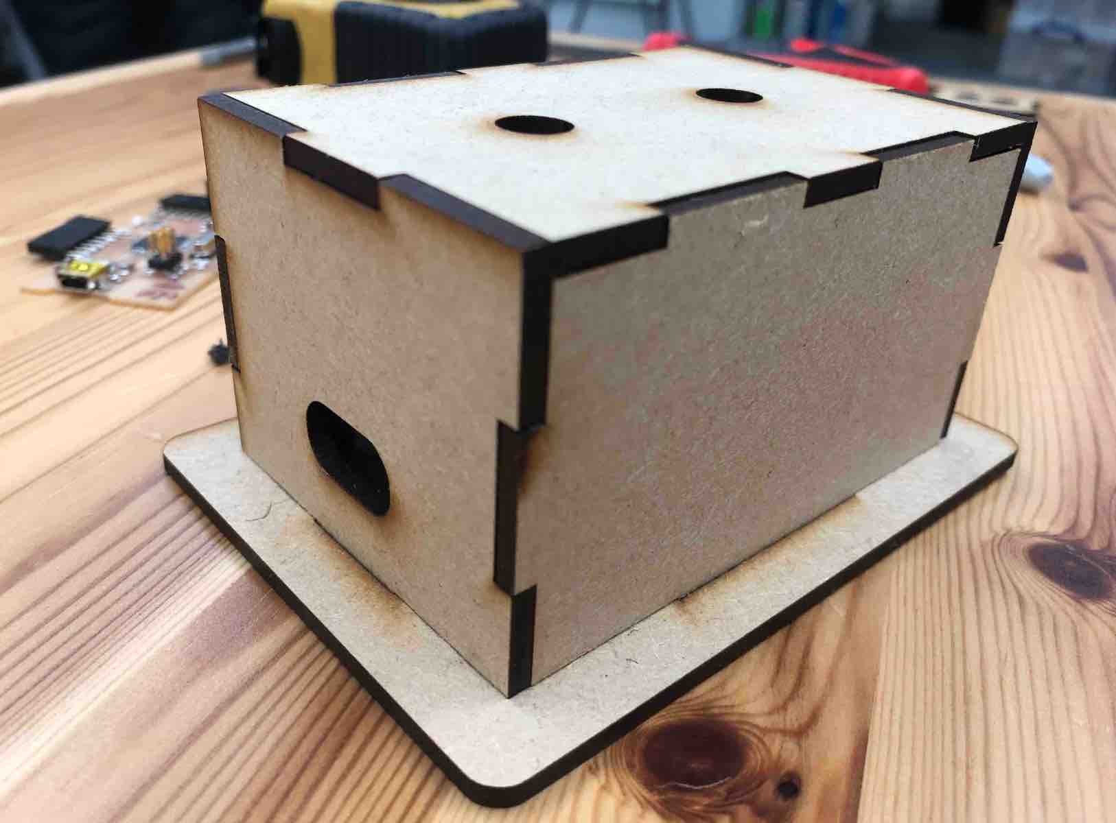
I also opted to rid the arm that comes with the servo and 3D printed my on servo heads to use. And we made a servo box to put all the circuit wires and boards inside...
We then attempted to trial MDF but then cut out enough holes in the arm so that it would be lighter. Unfortunetly this did not work out as well as hoped because when the second arm was then attached, the first arm had a hard time staying up straight, now having to carry the weight of not only the pens, but the arm and the other servo too.
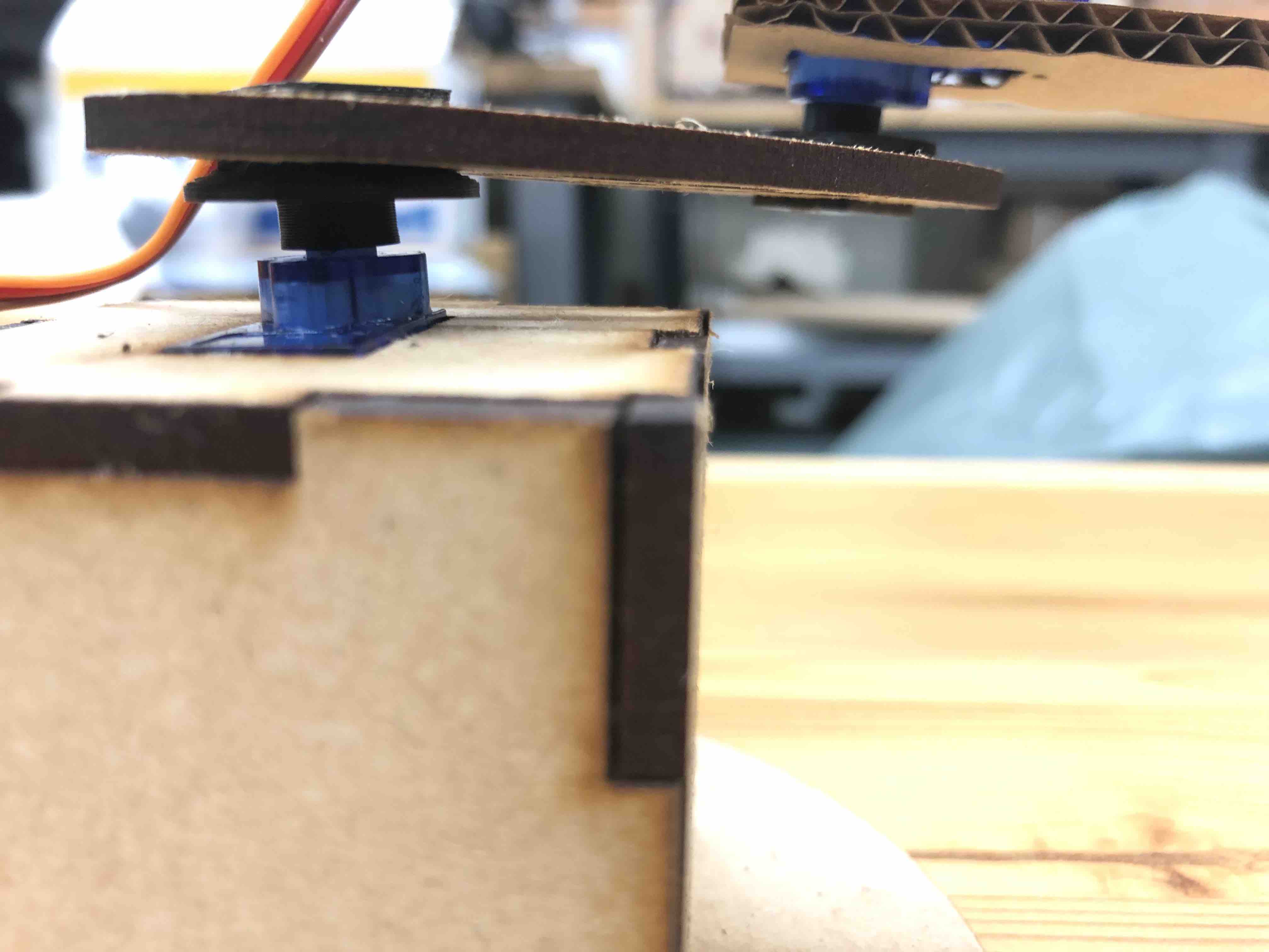
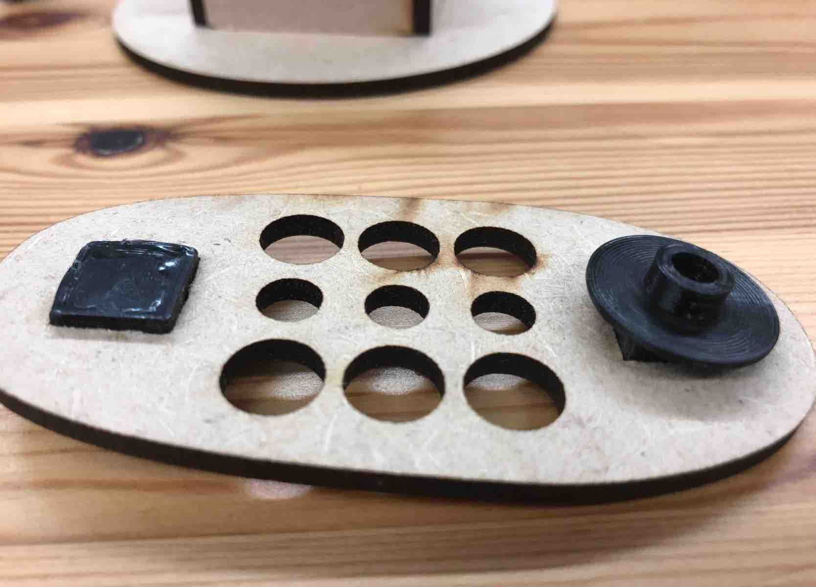
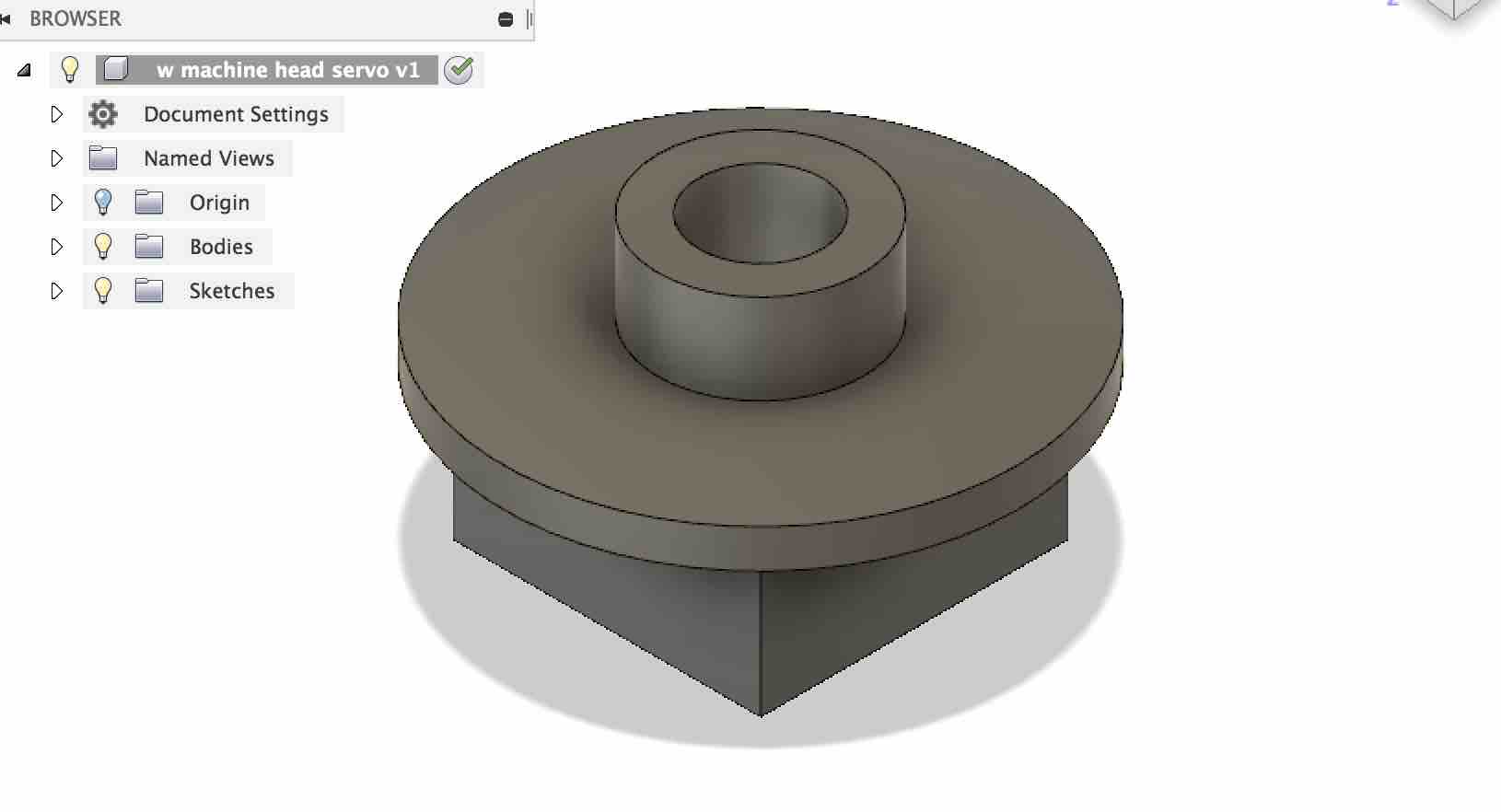
As for the servo head! That was 3D printed and created on Fusion thanks to my handy dandy measurements list. It only took 3 tries till i got a size that fit perfectly! Not bad for a somewhat rookie..ish ha. I made 2 of them.
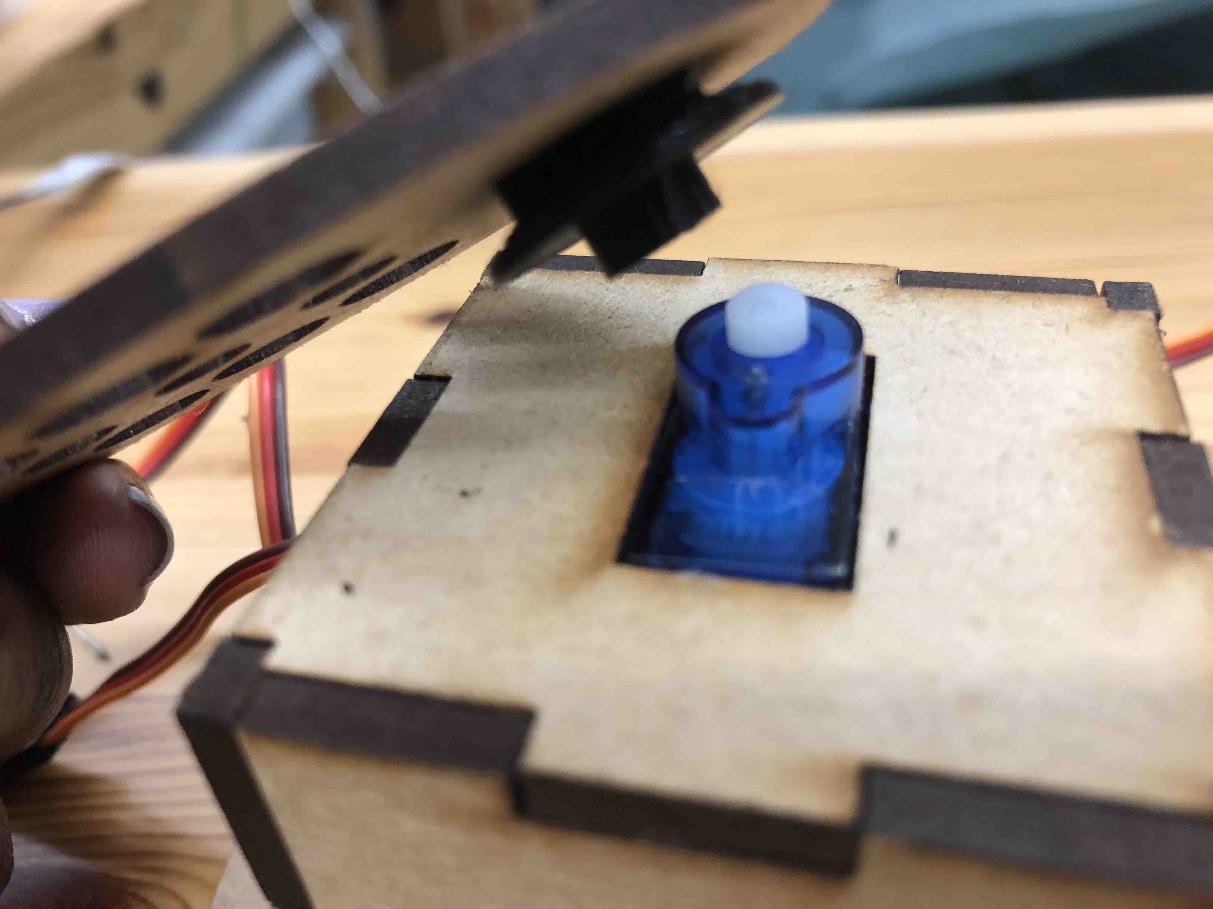
The idea was to replace the arms that come with the servo head because they were in the way, not truly needed and not exactly visually pleasing when looking at the machine as a whole. It needed to have a part to sit on teh servo head, something to stop it from moving (this is the flat circular bit) and something to help fit it through the hole (the box shape).
This weeks homework: