Although it took me two weeks, I managed to finally get a board done, and get it to function. I am still playing with getting it to do what I want, but I've taken some time to play around with what I can get it to do.
My board is a RGB LED board, that was intially to feature 5 RGB LEDs (specifically RGB LED WS2812) and a touch sensor, but due to running out of RGB LEDs (as they are ones that Luiz kindly gave me), it is now a star shaped board with 3x RGB LEDs and a tocuh sensor. The RGB LEDs are addressable which made things super nice and fun to code with. Speaking of fun....Fun point! - the touch sensor is a star shape too (STAR-CEPTION!)
I decided to push myself a little (I paid the price a little of this both space and time but it was sort of worth it), and make a star shaped board. The idea initially was to have a bunch of "stars" (LEDs)following the outside of the star shaped board. But then decided to first start simple and have 5 LEDs on the outside to test and if it works, make another where there are more.
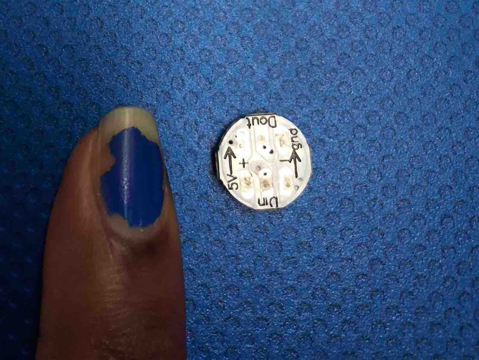
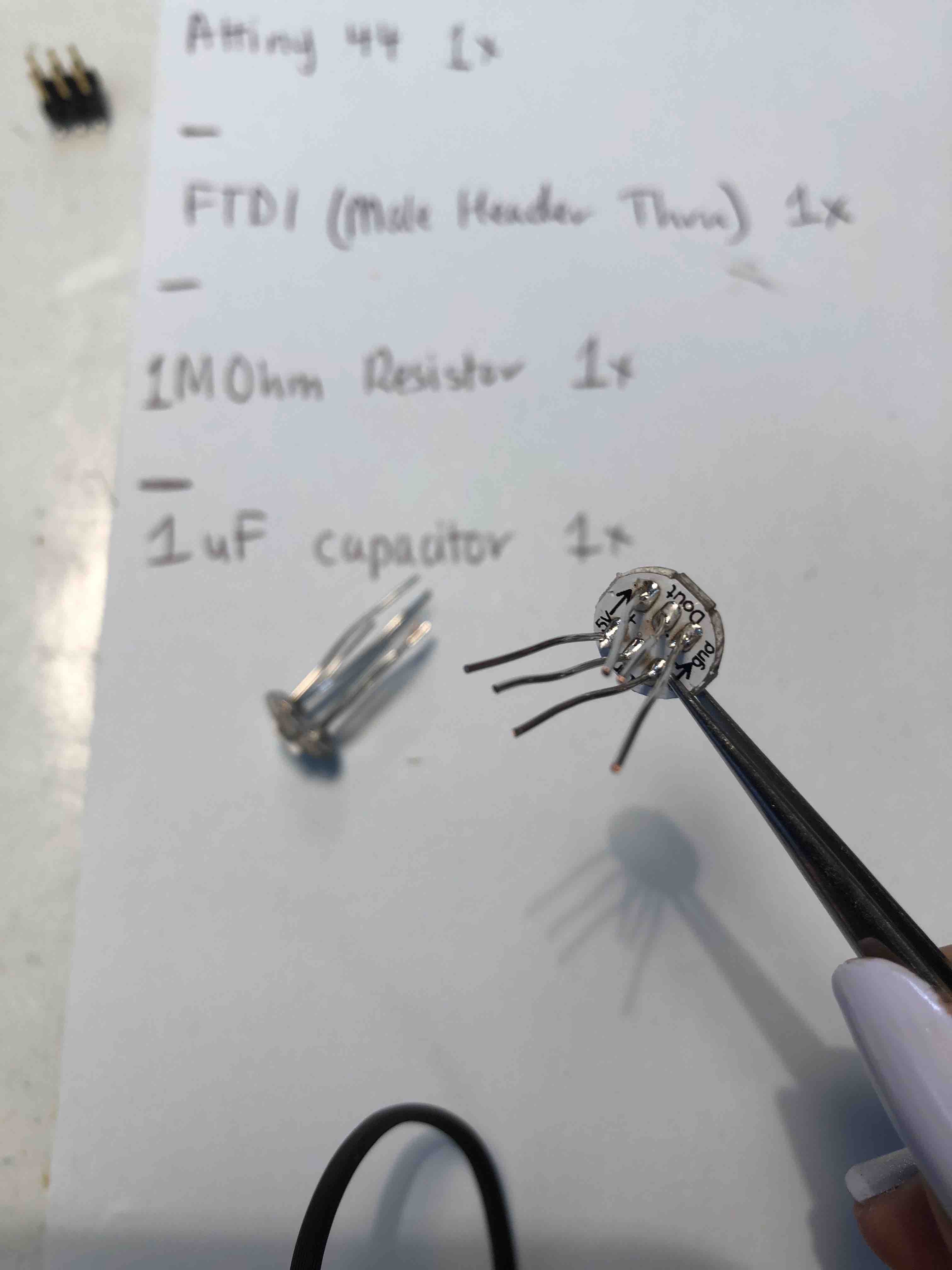
Luiz suggested to work a little towards my final project goal, I should use RGB LEDs, he had some which he kindly let me use, and so I set off to make a - what I thought was- simple star RGB LED board. Just to quickly show you the size of the LED, keep in mind I have baby sized hands and fingernails, also ignore my chipping nailpolish please!!!
It was extremely hard. A pain in my behind. In the end I only managed to have 3 RGB LEDs on my star board, and the top bit of the star was cut off a little (though you can't tell because I Filed it down to a curve). I also mucked up the order of my GND, VCC and pin traces, but we managed to still salvage it in the end and it actually ended up working in my favour visually because it makes the board cleaner and hides the components on from the view of others looking at the board.
When making my first one, I ran into problems understanding how to use Photoshop and Illustrator. This is due to two reasons:
Eventually I of course managed to solve both problems. Luiz suggested using my old programmer board to see what size the reshape my board to by using identical components e.g. the attiny and the 3x2 pin head. I also then later realized (simply because I did not know/realize), that I needed to crop my canvas to a little bit more than the outside of my board because this was also adding to the size that Fab Modules was referring to that I was confused about. I also learnt about the (IMAGE BOARD?) in Illustrator. Initially I had no idea what it was and would ignore it, but then my class mate Kyle explained that it is the equivalent to my canvas, so I needed to make it bigger in order to be properly reccognised.
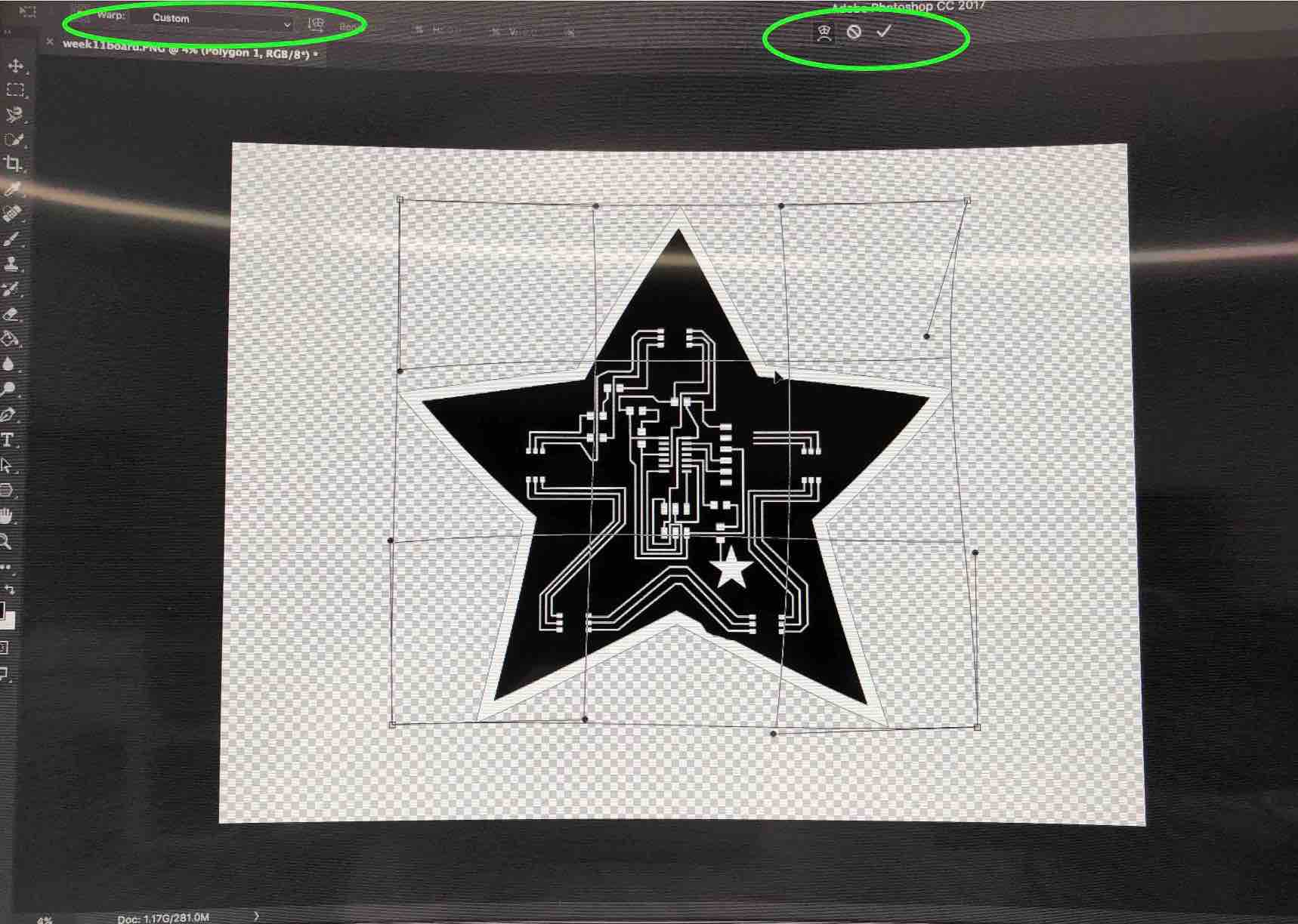
As for making the outline for my board, I did what I should have thought to do at the start, which is to ask google for help (*facepalm*). I am glad I did because I also made my board outline a little funky, so it's not just a plain star shape, but it is a bit distorted. I used the transform tool to reshape it when I was milling my second star board, to make the LEDS appear as close to the points of the star as possible. I also edited their placements in Eagle by shifting them upwards diagonally as I noted when I made my first board that they were really low on the side corners for my liking. Unfortunetly I ended up not using my transformed star shape, simply because I had decided to star from scratch with resizing my board and making an outline to eliminate all possible problems I was facing. But I were to redo this board, now that I know how to properly size my board, I plan to use this transform tool on photoshop to kind of keep things funky.
I did manage to align my RGB LEDs as close to the edge as possible though thankfully, althought this doesn't matter that much anymore now that the LEDs are on the other side of the board.
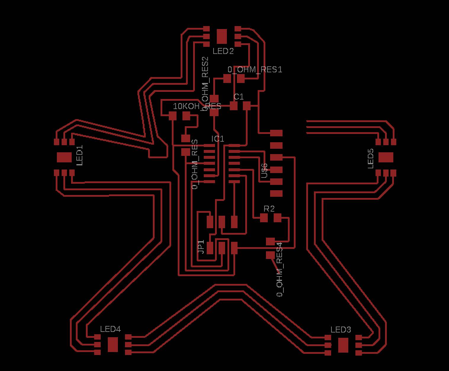
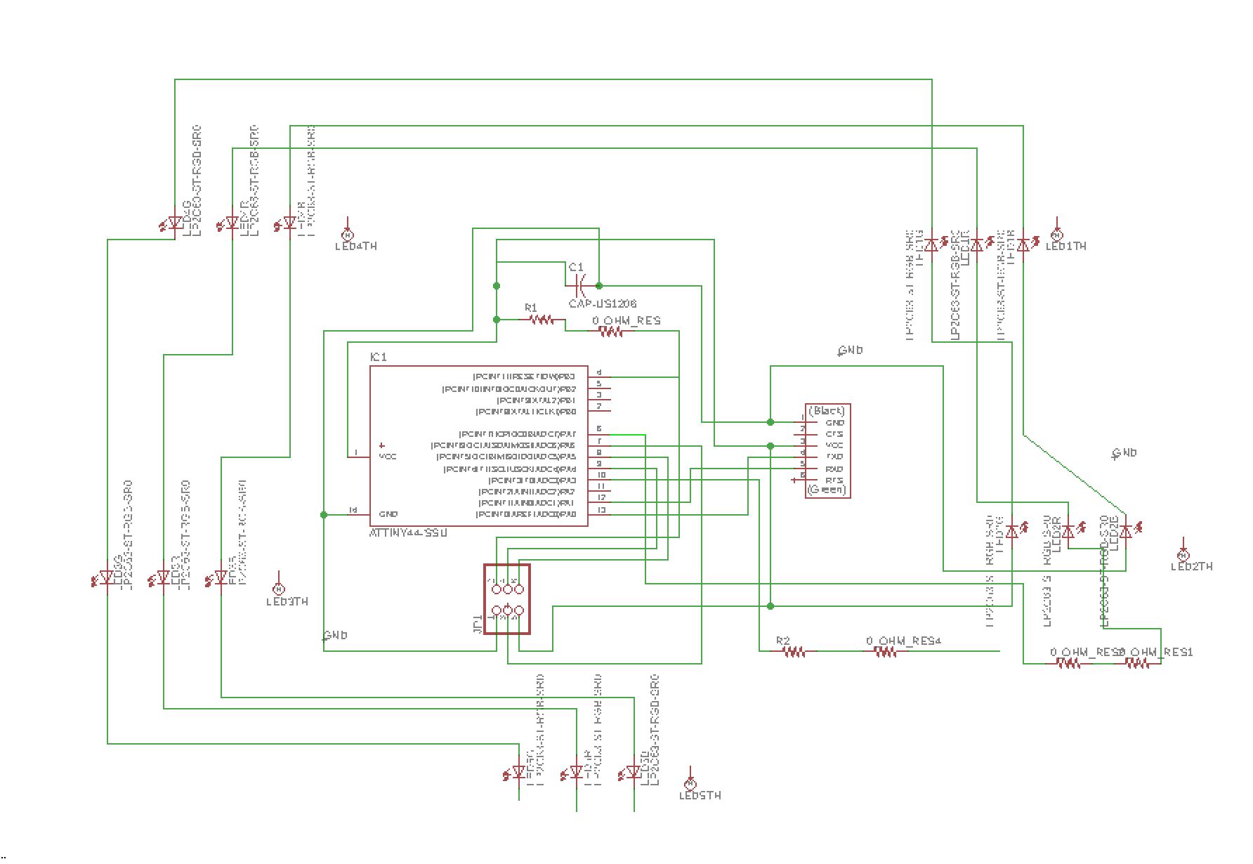
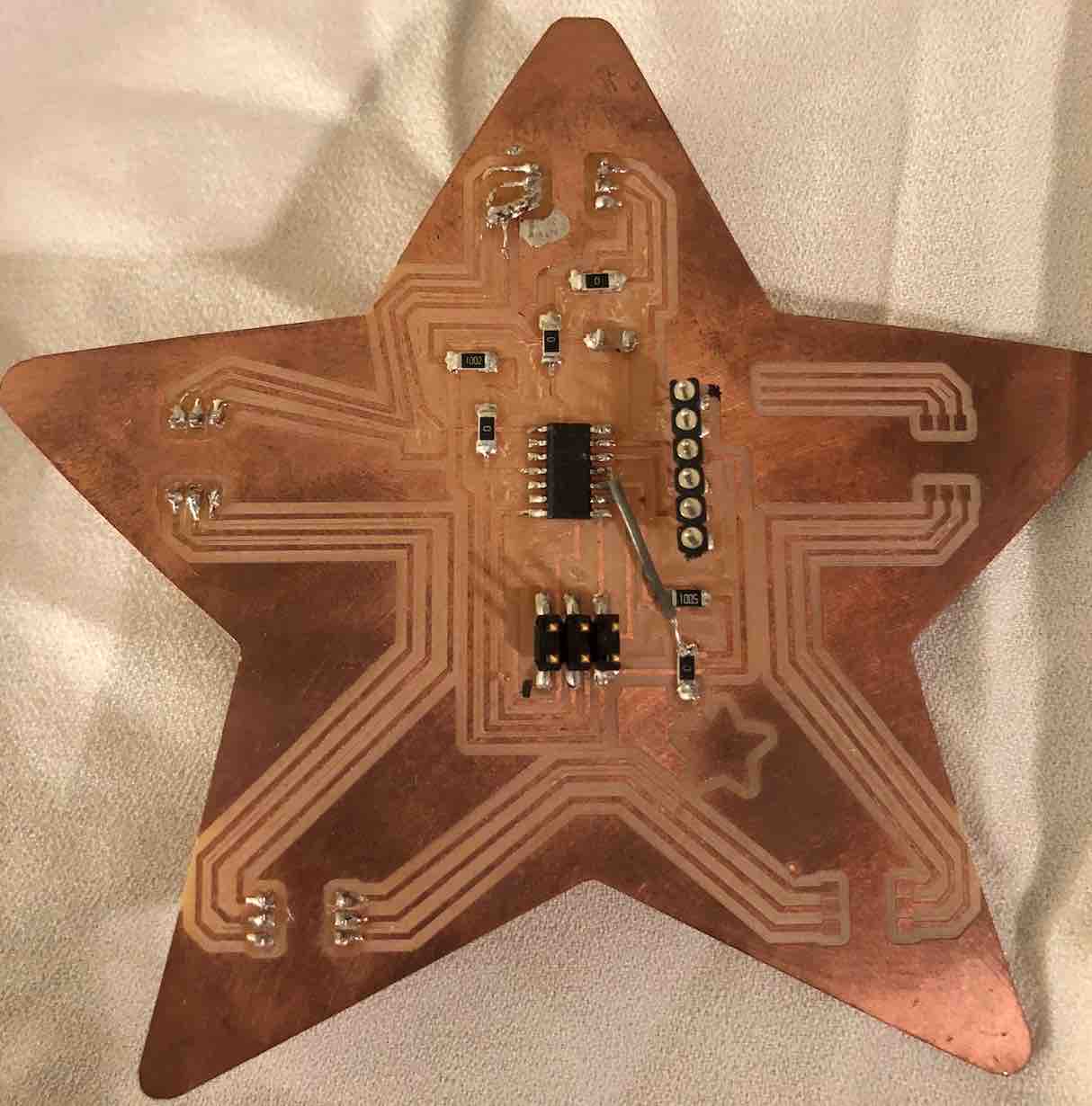
When making the first star board, I used a lot of 0 Ohm Resistors as jumpers because of problems with traces being locked in when going from my first RGB LED to my second one. One issue as well Luiz suggested when it was all soldered and the first attempt at programming the RGB to switch on, is that I had a trace running through my capacitor. He pointed out that another class mate of mine, Andrew, had his running through too and it had caused him some issues. Luiz brought this up becase my RBG LED wasn't always lighting up and we couldn't figure out exactly why.In attempt to solve this, we desoldered the capacitor and soldered it in a new way - using it on its end, and then soldering a wire above the board from the other end of the capacitor to the VCC FTDI pin.This seemed to get it to work. So I kept that in mind when I was re-creating my second star board.The board and schematic now look like this:
Upon having soldered everything else other than the RGB LED, I realised I had messed things up and confused myself when I was creating my board in eagle in terms of which trace goes into which part of my LED component. I had mixed up my VCC and GND traces. Since the board wasn't TOO great, we decided to simply flip the LED around and solder it on to at least test it's functionatlity before I went ahead and soldered them all on the Star board 2.0. Luckily it worked well..though sometimes the singal would cut. I think it might just be due to the way the LED might have been soldered on. And sometimes the jumpers weren't connected between the programmer, or the arduino and my board.
When making my star board 2.0, I managed to solve my little 0 Ohm Resistor Mania issue. It was simply that I had my traces to my RGB LEDs incorrect. It was a hunch I had (that it was incorrect, not that it would solve my 0 Ohm Resistor dillema). So I asked my class mate Kyle about it. We then both realised that it was indeed incorrect and it was down to the fact that though I though I understood how the current flows in the circuit for LEDs, I alas did not. I did some research finding a page, and it brought up more confusion than it was preventing/solving. I was finding it hard understanding what Kyle was telling me and what I was seeing on the site. Kyle then explained to me that on the site, while to me it looks like the current is flowing INTO the LEDS, where in actual fact it is flowing OUT of them. My board in the end went from having a complicated system that included 5 0 Ohm Resistors, to a simpler (and cleaner) 4x 0 Ohm Resistors. In both cases, one of the 0 Ohm Resistors is dedicated to my touch sensor. But in my first board it was to solve the traces being locked in. In the second board, it was to solve the capacitor issue so that my pin7 trace does go through the capacitor but over the traces.
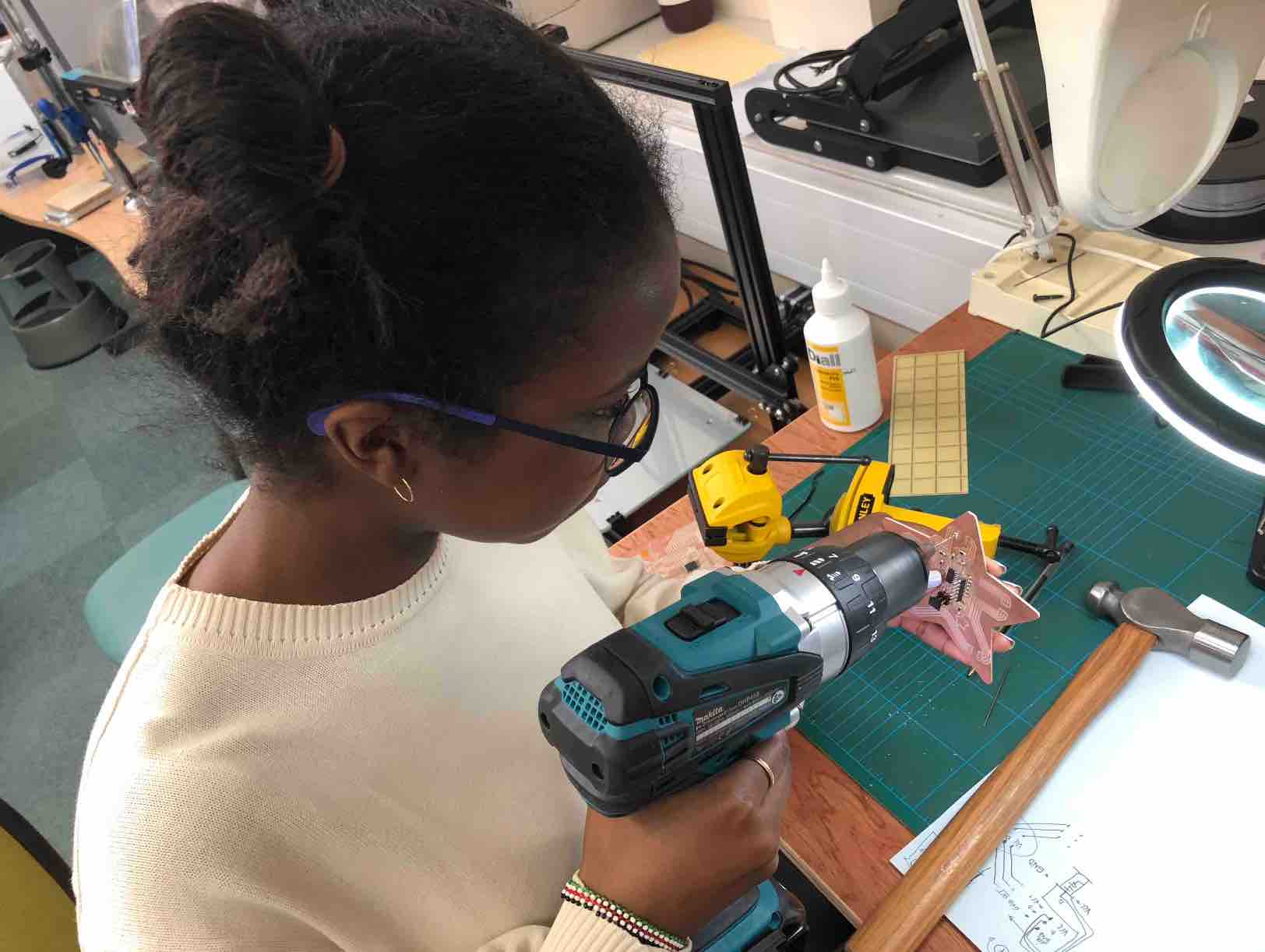
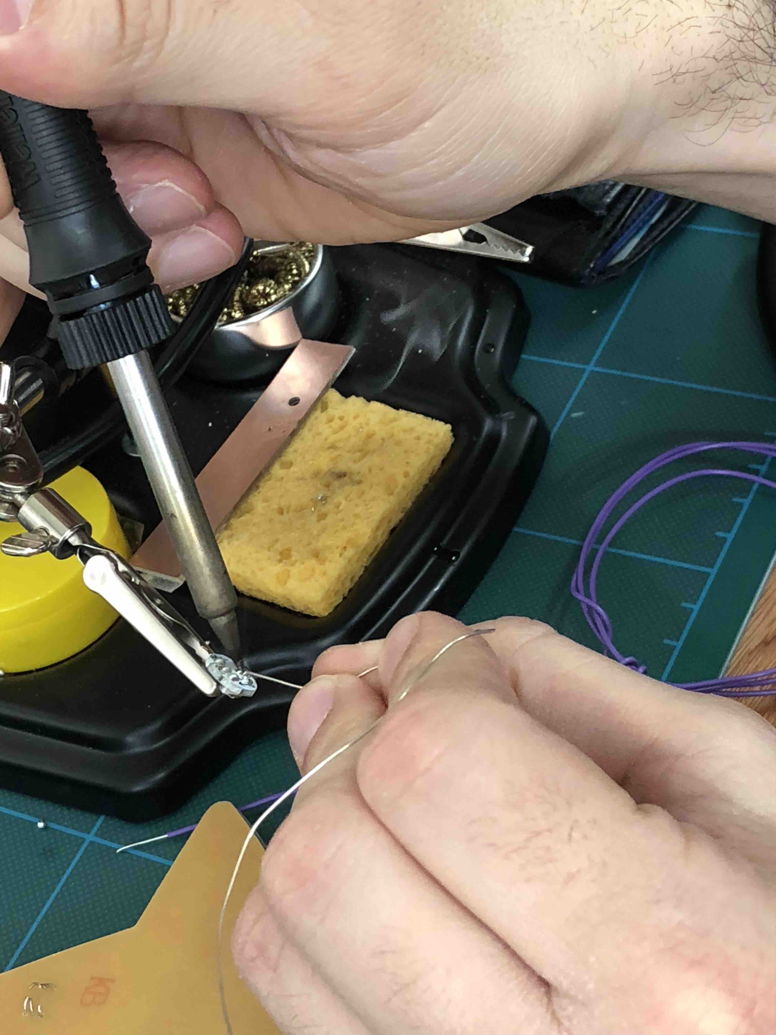
Although my new board was much cleaner with less 0 Ohm resistors being needed, I had forgotten to flip my VCC and GND around as I was so focused on getting the ins and outs for my LEDS correct. This time around, instead of soldering the RGB LED onto the board, Luiz smartly suggessted to drill hols in the places where the LED would need to go, and solder the LEDS onto the back of my board. We don't have the correct collet for the dremel drilling bit. So the below video was a demonstration using an improvised method which turned out to still be effective. Though this was a mistake, it ended up being a happy mistake! As now when I look at the board, you see the LEDS and not all the other components sticking out (not that my soldering skills look messy!!). I just felt it made the board look much cleaner. Below a video on how I was taught to drill the holes.
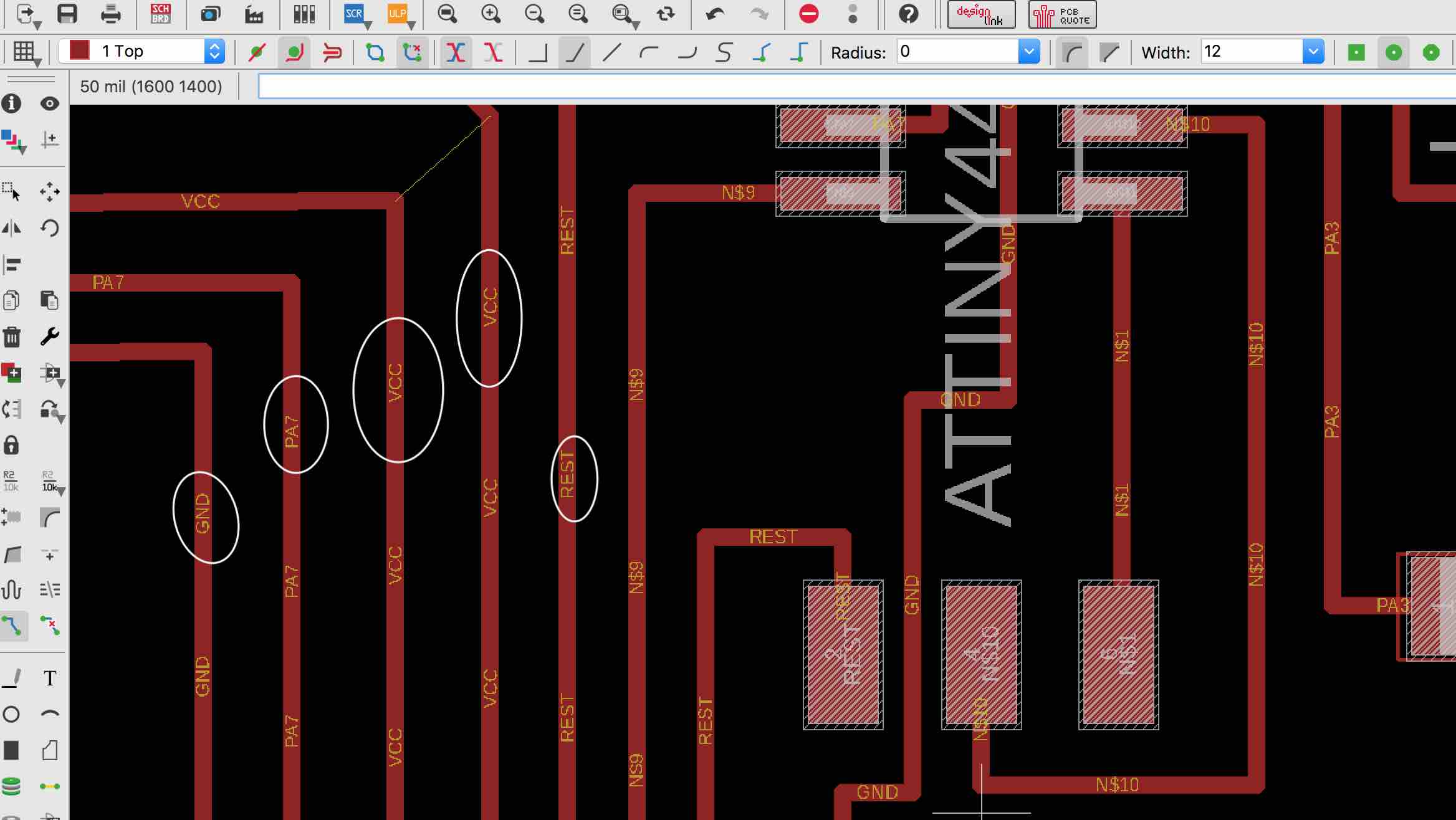
In the process of learning how to use Eagle better through trial and error and lots of hovering over things, and clicking on them to find out what they do, I discovered how to label my traces. This is something I've been wanting because when I'm zooming into sections to double check them, it has been annoying to constatnyly have to zoom in and back out and in again in order to double check where the trace is coming from or leading to. This has saved me a lot of effort.
I also figured out how to maniplate traces more. This has been a handy skill for my star because I have had more controll over how I want it to be shaped.
px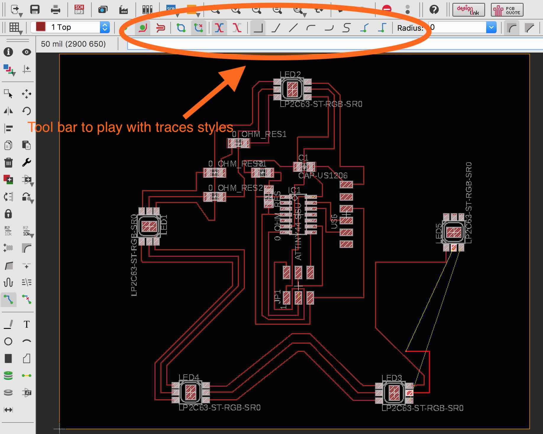
Before making my 2.0 Star Board, I needed to clean the MDF surface because it was bumpy from all the previous milling. Luiz graciouly taught me how to do it too
Then I got to soldering on the LEDS...Luiz demonstrated the best method to use when doing so and I then went and completed the rest..
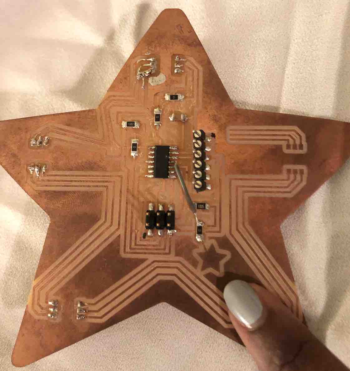
And this is what the board looks like :) In the second image I am pointing to my touch sensor (remember my star-ception joke? No? ok cool....)
As previously stated, I had mucked up and forgotten to flip my VCC and GND around...but we still had a go to see if the board would even work...so we soldered it onto one side and lo and behold it did! So at least I got that part right...
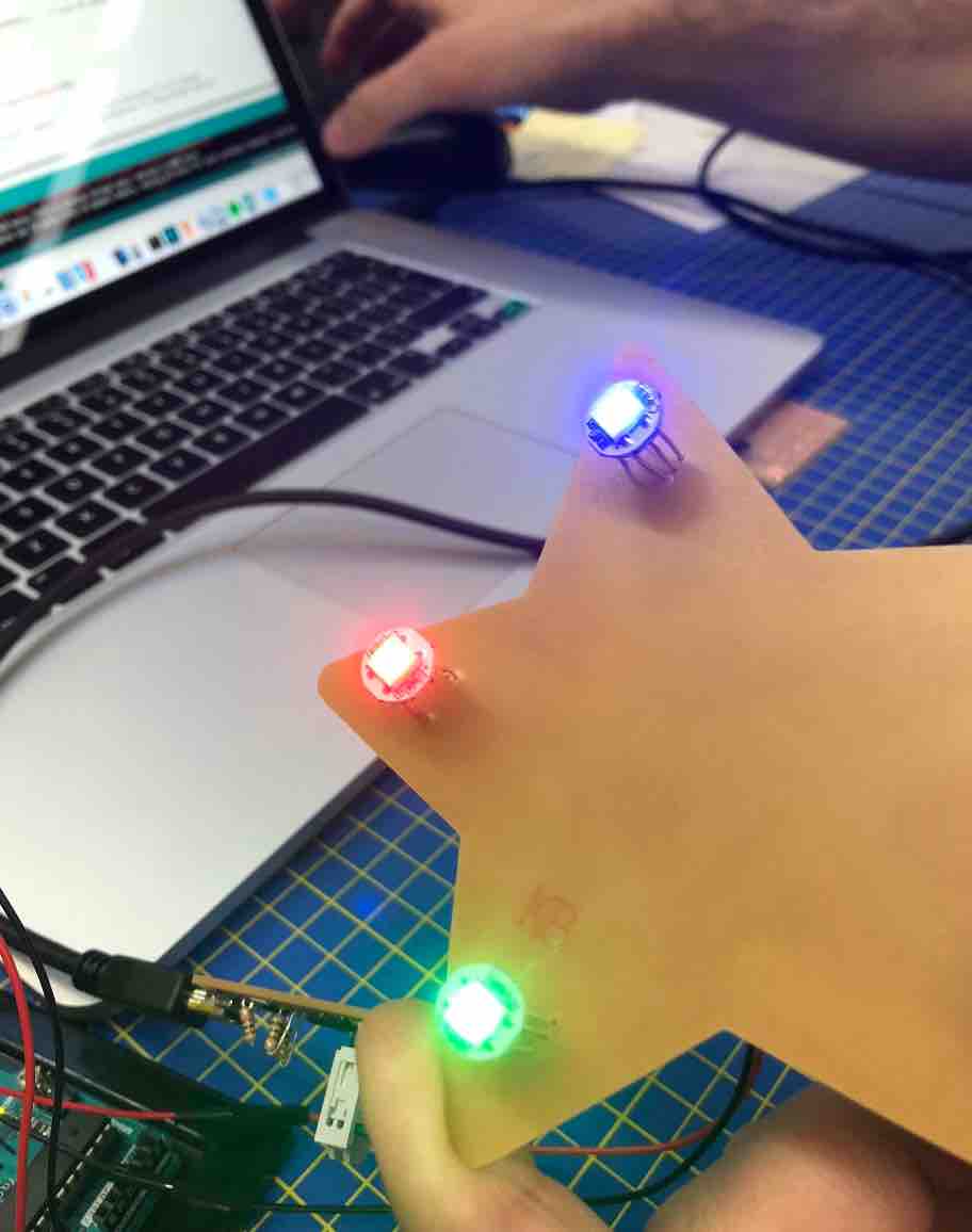
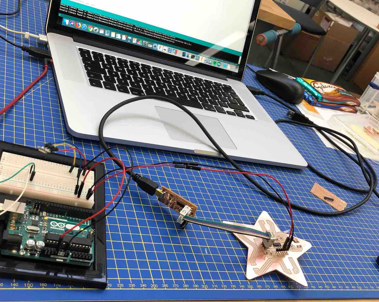
After I drilled the holes and soldered the LEDs in, we went ahead and tested out the code to see if it was (and it was) functioning! BEHOLD!
We did have to fiddle a bit with the code to get it to work, but eventually we figured it out, and then I went ahead and altered it to my liking :)
This is the code I used to create my glowing twinkles (below download link name: Star board code
   // use the cRGB struct hsv method
#define USE_HSV

#include <WS2812.h>

#define LEDCount 1
#define outputPin 7

WS2812 LED(LEDCount);
cRGB value;

int h = 214;   //stores 0 to 614
byte steps = 15; //number of hues we skip in a 360 range per update

byte sat = 255;
byte val = 255; // was 127 _ this is the brightness

long sleep = 100; //delays between update

void setup()
{
  LED.setOutput(outputPin);
}

void loop()
{
  Cycle();

  for(int i = 0; i > LEDCount; i++)
  {
      LED.set_crgb_at(i, value);
  }
  // Sends the data to the LEDs
  LED.sync();

  delay(sleep);
}

void Cycle()
{
  value.SetHSV(h, sat, val);

  h += steps;
  if(h > 360)
  {
      h %= 360;
  }
}

Sophie Kiarie, Fab Academy 2018
And this is the final code that I then used (found under the title final code below):
        int ledR = 3;
int ledG = 5;
int ledB = 6;           // the PWM pin the LED is attached to
int brightness = 0;    // how bright the LED is
int fadeAmount = 5;    // how many points to fade the LED by

// the setup routine runs once when you press reset:
void setup() {
  // declare pins to be an output:
  pinMode(ledR, OUTPUT);
  pinMode(ledG, OUTPUT);
  pinMode(ledB, OUTPUT);
}

// the loop routine runs over and over again forever:
void loop() {
  // set the brightness of pin 9:
  analogWrite(ledR, brightness);
  analogWrite(ledG, brightness);
 // analogWrite(ledB, brightness);

  // change the brightness for next time through the loop:
  brightness = brightness + fadeAmount;

  // reverse the direction of the fading at the ends of the fade:
  if (brightness <= 0 || brightness >= 255) {
    fadeAmount = -fadeAmount;
  }
  // wait for 30 milliseconds to see the dimming effect
  delay(50);
}

     Sophie Kiarie, Fab Academy 2018
RGB require Since the LEDs are addressable, the LEDs are being powered by the external power supply :)
This weeks homework: