Sidenote: if you want to stopthe warmup, press the RED button on the keyboard with the spinning disc on it.
sidenote: +- controlls the gantry's speed
sidenote: "F" + "13" takes gantry back to XY 0.
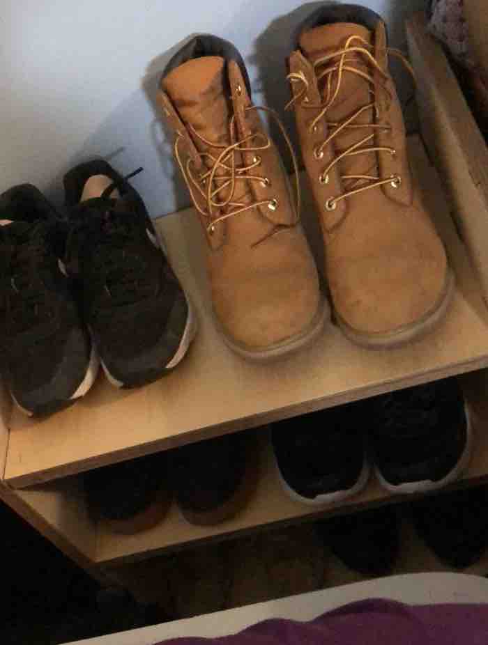
This week ran smoother than the last two. We were to create "something big". This was by far the biggest thing I've made. I decided, like the other projects, to make something I could actually use rather than something random which I would later throw out. I decided to make a shoe rack as all my shoes used to lie on the floor next to my bed and I wanted some organization.
Making the shoe rack was harder than I expected it to be but also quite rewarding in the sense that I now have a functioning shoe rack, and I learnt to use fusion much more and I am now more comfortable with it. It's the software I decided to use for this project.
After Neil's lecture on Wednesday, I was inspired by the japanese style of construction as I love how it looked so elegant and simple yet complicated. So afterwards I went and had a look at some designs online for inspiration to use for my shoe rack.
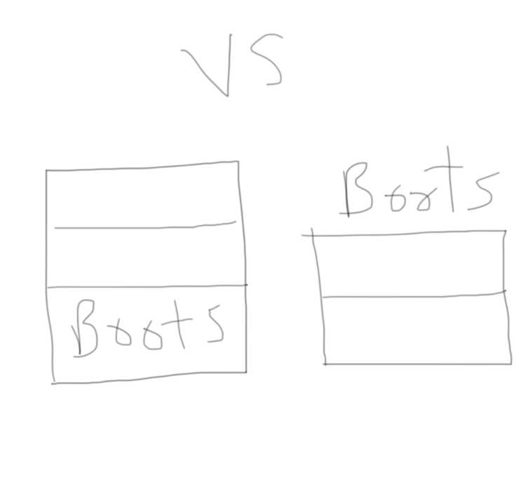
I decided I wanted to implement these two designs
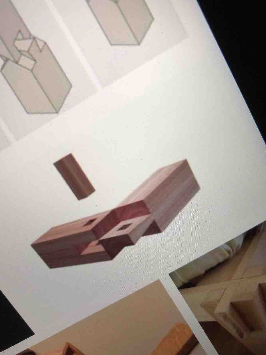
The image on the left was for the top and bottom shelf, and the second image for the middle shelves.
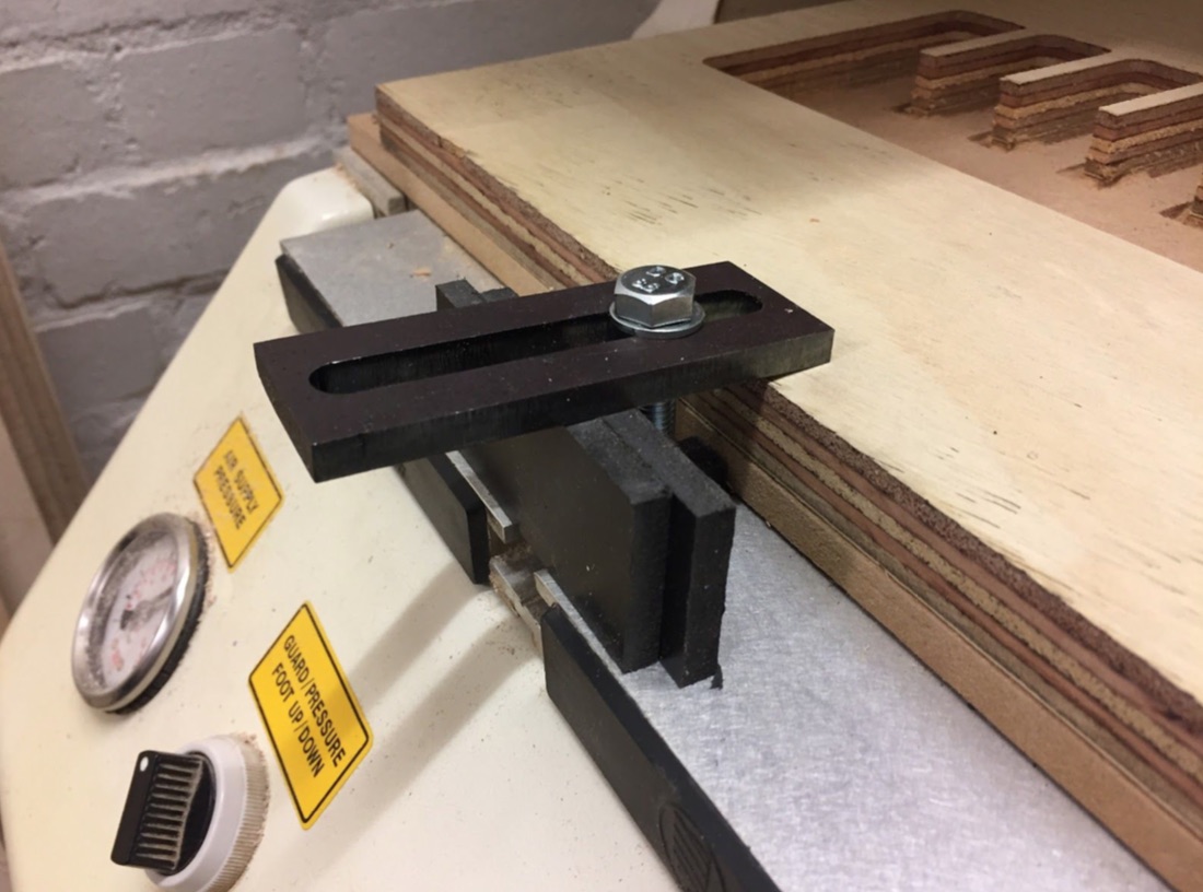
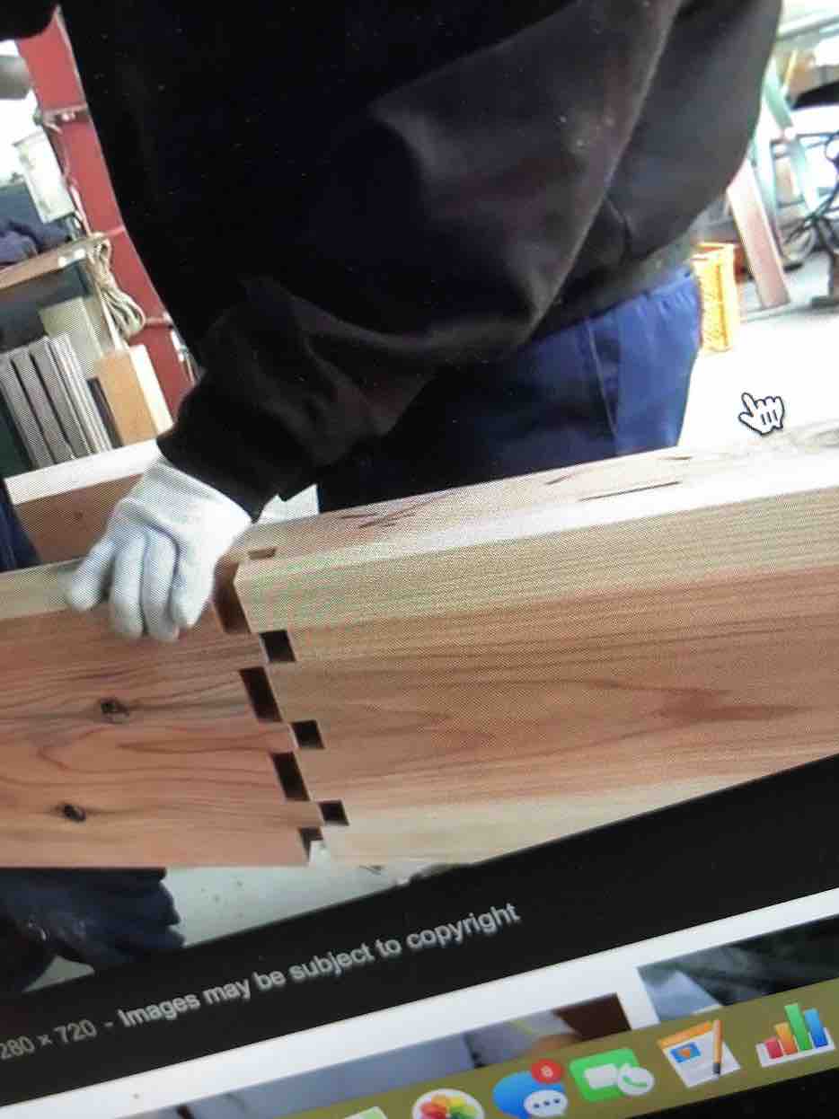
I also found more inspiration ideas for concepts similar to the japanese one to use whilst working in the CNC machine room at Grande Parade:
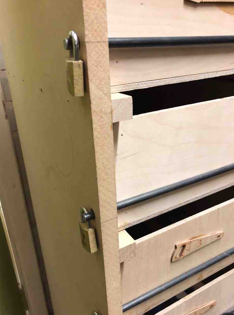
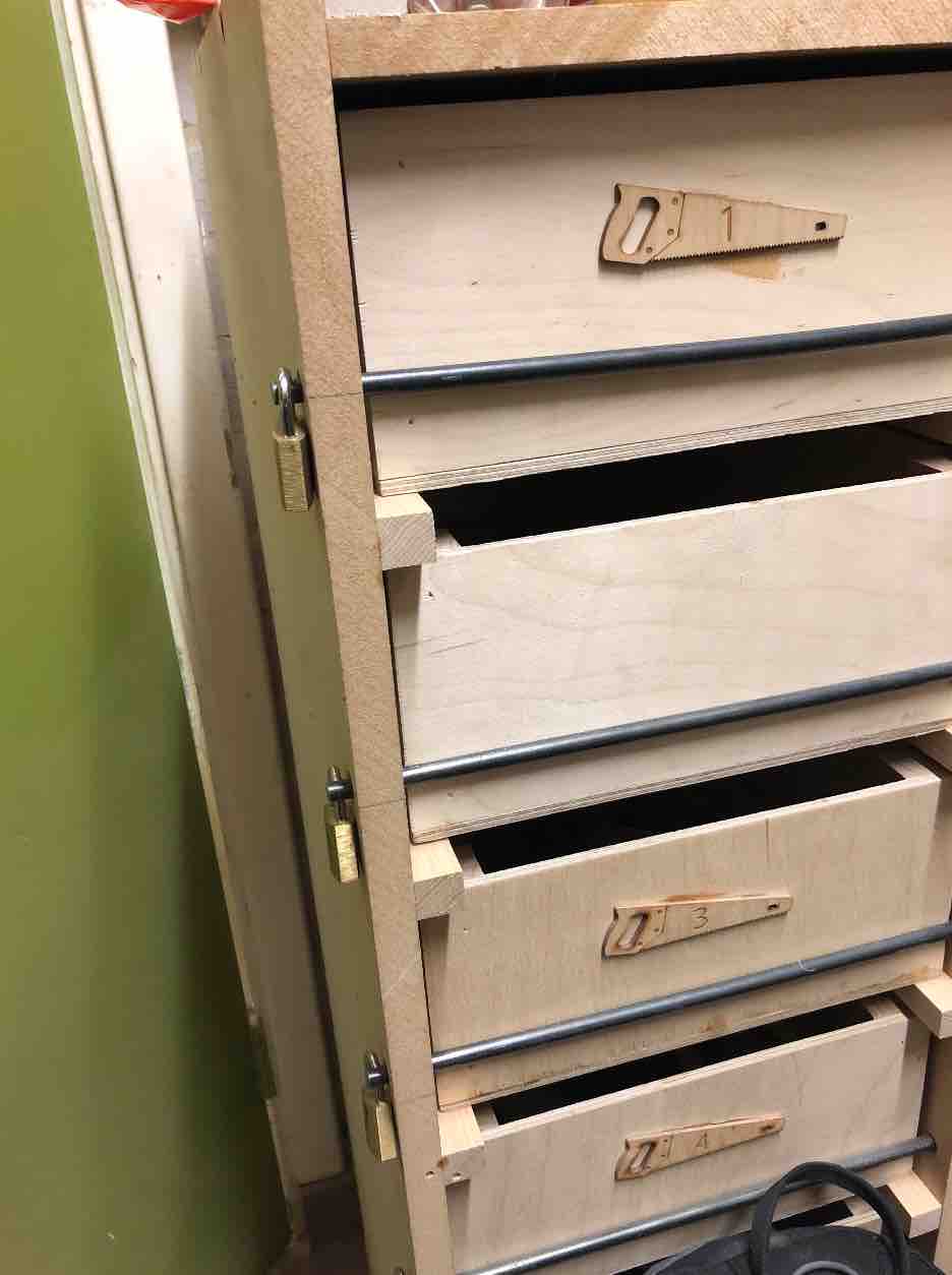
If you look closely, you can see that they have cheated here a bit with locks, but I'm pretty sure the locks are for security rather than cheating related reasons. But nonetheless a smart idea if my rack fails haha. I also see that they use a block to hold it in place, which is similar to what I plan to do.
I also had to have a look at how I wanted to shoe rack to look like. I had to ideas. Either have it all enclosed on have it so that the top shelf is open. I ended up deciding to go for a closed structure. This is because it means that I can use it for other purposes, whether that means the product I cut, or if I go back to my design later to use it as a CD rack or book shelf, or anything really.Below I have a diagram that is a rough one to have a sort of visual look at how they look.
Initially I wanted each shelf to fit 3 shoes, but the space I wanted to place the shoe rack in my room wasn't big enough to fit 3. So I went with two. I mixed and matched shoes to get a length of them. I did this so that I could figure out which shoes best fit on which shelves and their parings. I own 7 pairs of shoes so I needed 3 shelves. I say 3 instead of 4 because At almost all times, 1 of the 7 pairs of shoes I will be wearing as one of them are house shoes, so this wasn't an issue for me. I own 2 boots, so I measured how high they went and added a few cms to them so that it isn't a tight fight. I chose the bottom shelf to be the one that holds the boots. I also measured the heigh of my other shoes, which are all mostly sneakers, and again added a few cms for spacial reasons.
Knowing that we were being given 2x1m sheets of plywood to mess with for first trials, I kept its dimensions in mind when constructing on fusion. Using a measuring tape I borrowed from my flatmate, I took down some measurements of the height of the boots + height of the sneakers + (the width of the plywood)x3
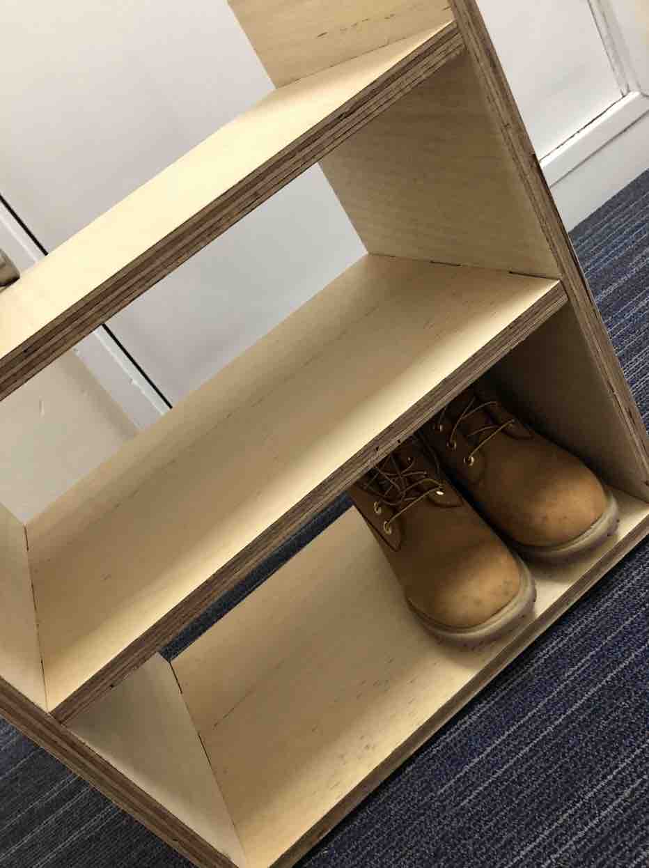
This figure ended up being the height that the pillars of the shoe rack were to be. It also was my guidline to see where each shelf would slot in. This ended up being a bit of a fall through later in terms of my calculation because the boots shelf ended up being just a little under. Meaning there is not space. I believe the reason for this is because I forgot to add one more width of the plywood to my calculation - I had forgotten to take into account the bottom shelf. Nonetheless all shoes fit fine.
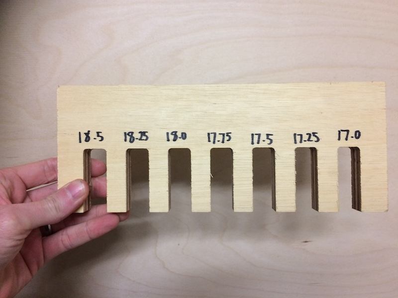
Because we could only cut a group at a time per day, I decied to go later in the week as I had University classes most of the set other days. As a group on the first day, we created a comb using the big milling machine. Having made this helped me with my construction on Fusion later because it informed me which sizes to make my slots later. This was especially important because I was doing the Japanese construction style.
I began with the bottom most shelf and worked my way from there, the side shelves, the top and then the middle shelves. I kept alternating between using the line tool and the rectangle tool. This is because it made more sense for some of the shapes to draw the slots and others it made more sense to extrude them later.
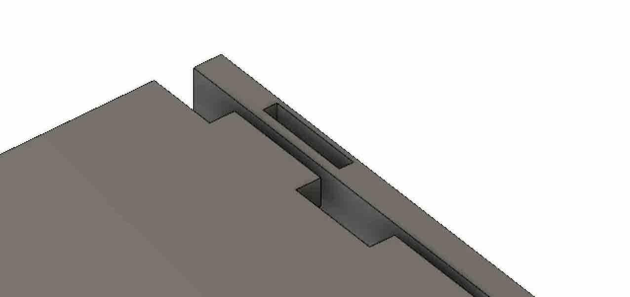
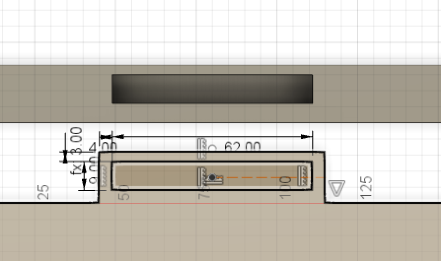
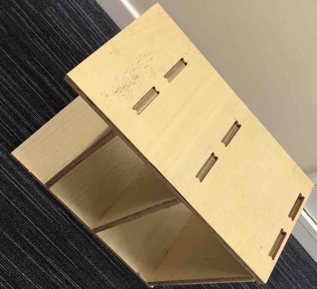
Making the top and bottom construction was the hardest because it required a lot of deep thinking. I had to look at the thickness of my wood, and then look at how much space between the end and the hole there should be in order for the shelf to slot into the pillar but at the same time but stuck in hard once I put in my block as of course too small would mean that the end would be fragile. This is a closer look at it.
..And a comparison between all the horizontal shelves (the ones that hold the shoes)...
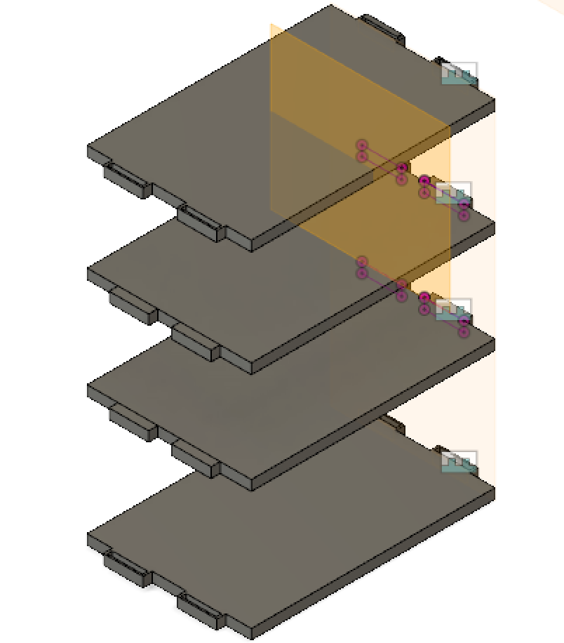
In oder the get the extrusions for the top and bottom shelves, I had to extrude the side shelves twice. Once on the top and then again on the inner side of the shelf
I had Kyle assist me with some bits on Fusion such as how to mirror my objects to save myself time. This tool was helpful because in reality, there are only 3 different shape styles;
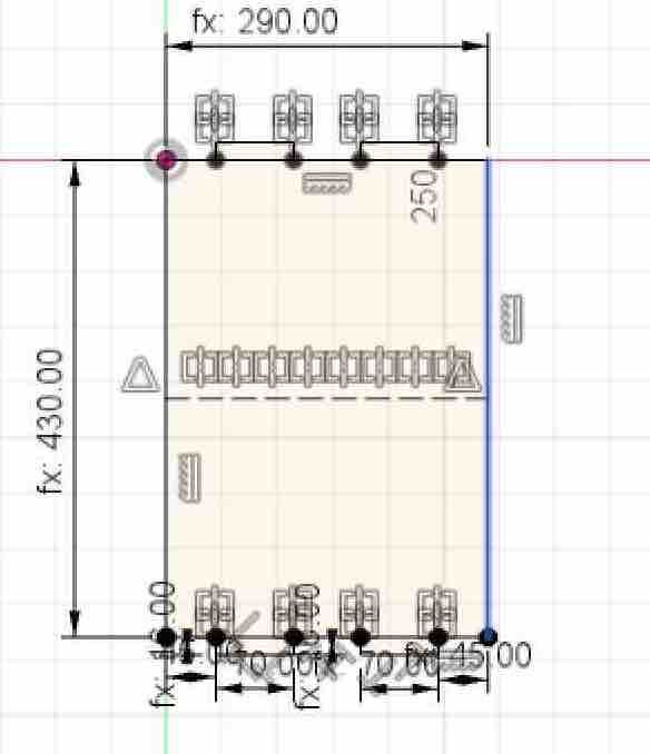
It also meant that everything would be the same and less chance for error later in production. I also implemented set parameters in Fusion so that my shoe rack was adjustable and if I changed something, I wouldn't need to go and change each and every bit as really this shoe shelf was 3 parts; the pillars, the top/bottom shelf, and the middle shelves. It would also serve as a helpful tool to have if I wish to alter the shape or perhaps remake or make a bigger/smaller shelf later or in the future. Below is the final look.
To aid myself when making the slots, I drew it out on paper to properly visualize and try calculate what was what. It also helped because it meant I didn't have to keep switching between sketches to find out dimensions because I had them written down next to me.
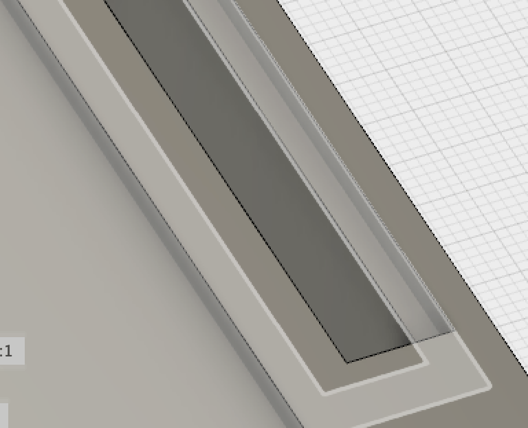
When making the slots, I had to keep in mind the thickness of the wood, as well as what the minimum would be to extrude before it becomes to fragile to use as a result of snapping and breaking.For this part I made the holes/slots by creating sketches on to the shelves, then extruding those sketches through cutting
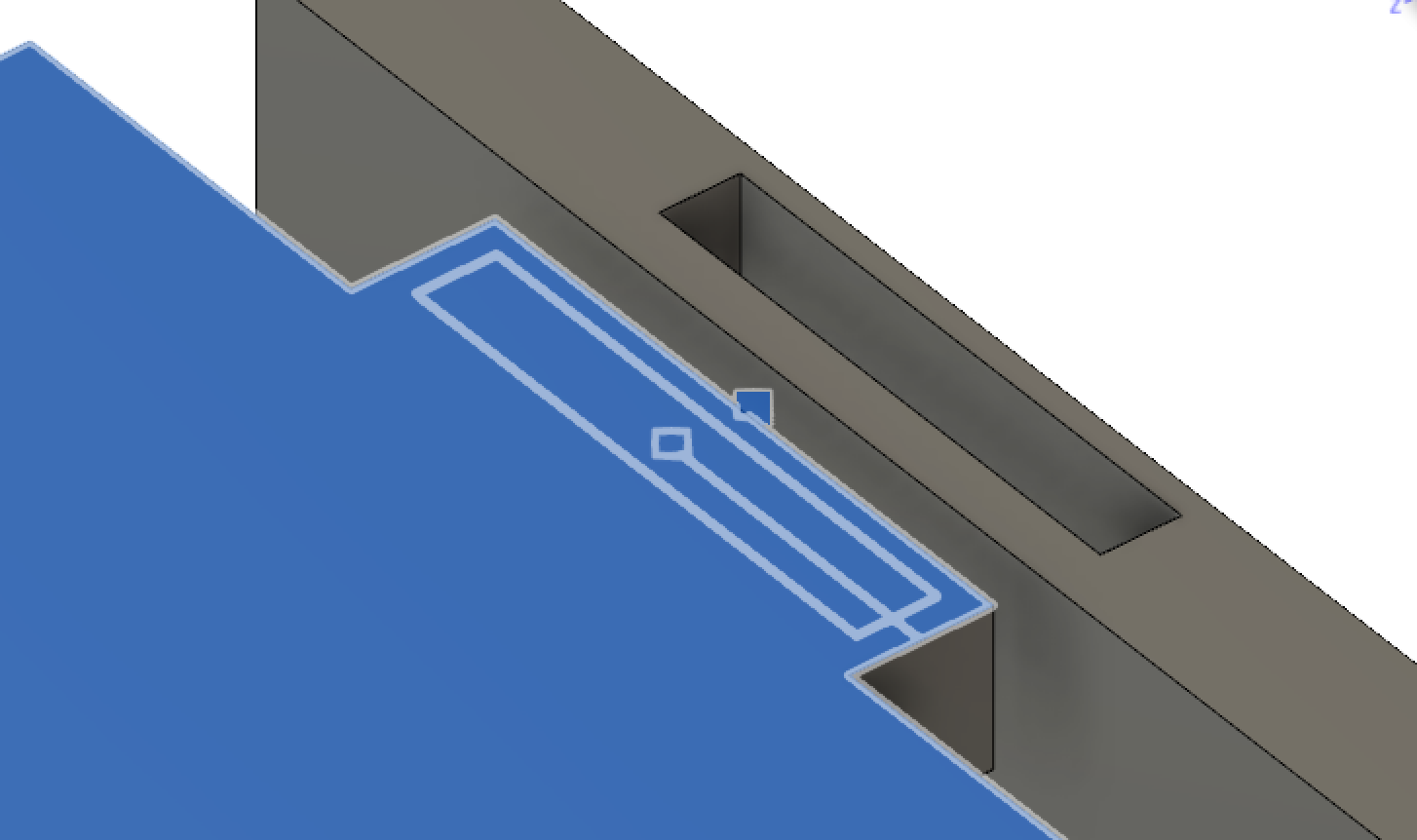
As you can see, they are quite thin, but I believe that they would've sufficed when taking into account that I was using the Japanese construction style so the block in the center would have been able to support it and sliding in into the middle shelf should not proove as much an issue.
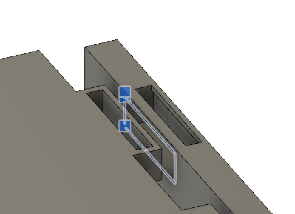
When creating this section of my shelf, I decided to make the side shelf's top hole, then the middle/top shelf extrusion followed by the inner side of the shelf's hole last. I did this because it helped me better work out what dimensions I needed things to be to slot in nicely.
Unfortunetly come Tuesday, I was informed that my shelf wouldn't work in terms of the top and bottom shelf mechanics because the CNC machine that we had access to was not capable of doing so. This meant having to change my shelf. Due to my limited skills in Fusion I had problems initially trying to change my shelf so that I could cut it. That was frustrating as all that I needed to do was to just change the top and bottom shelf to match the mechanics of the middle shelves, but I didn't know how to mirror them as some bits were extruded inwards on the pillars.
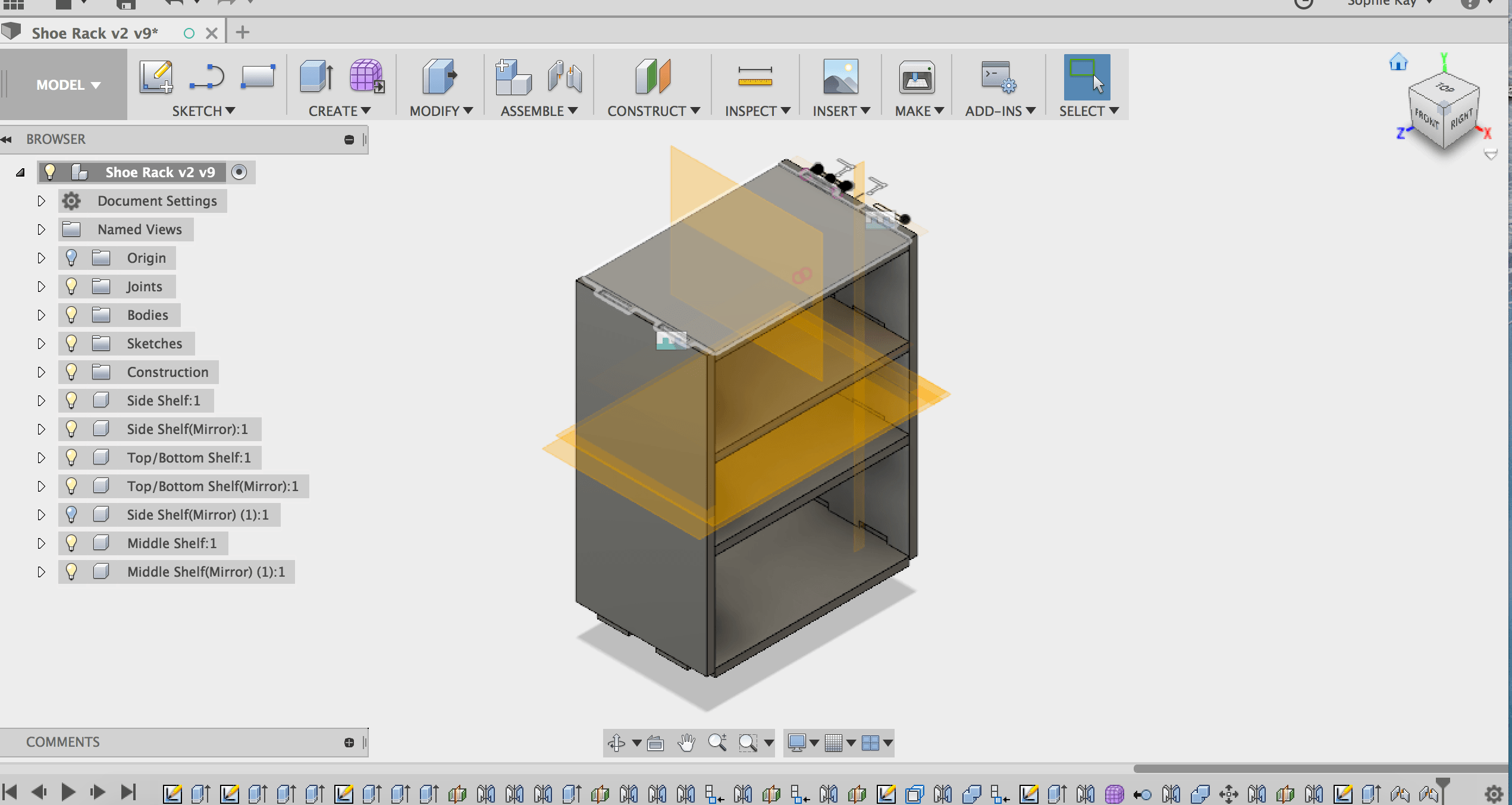
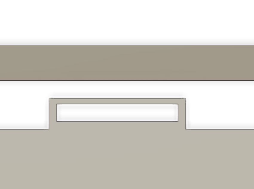
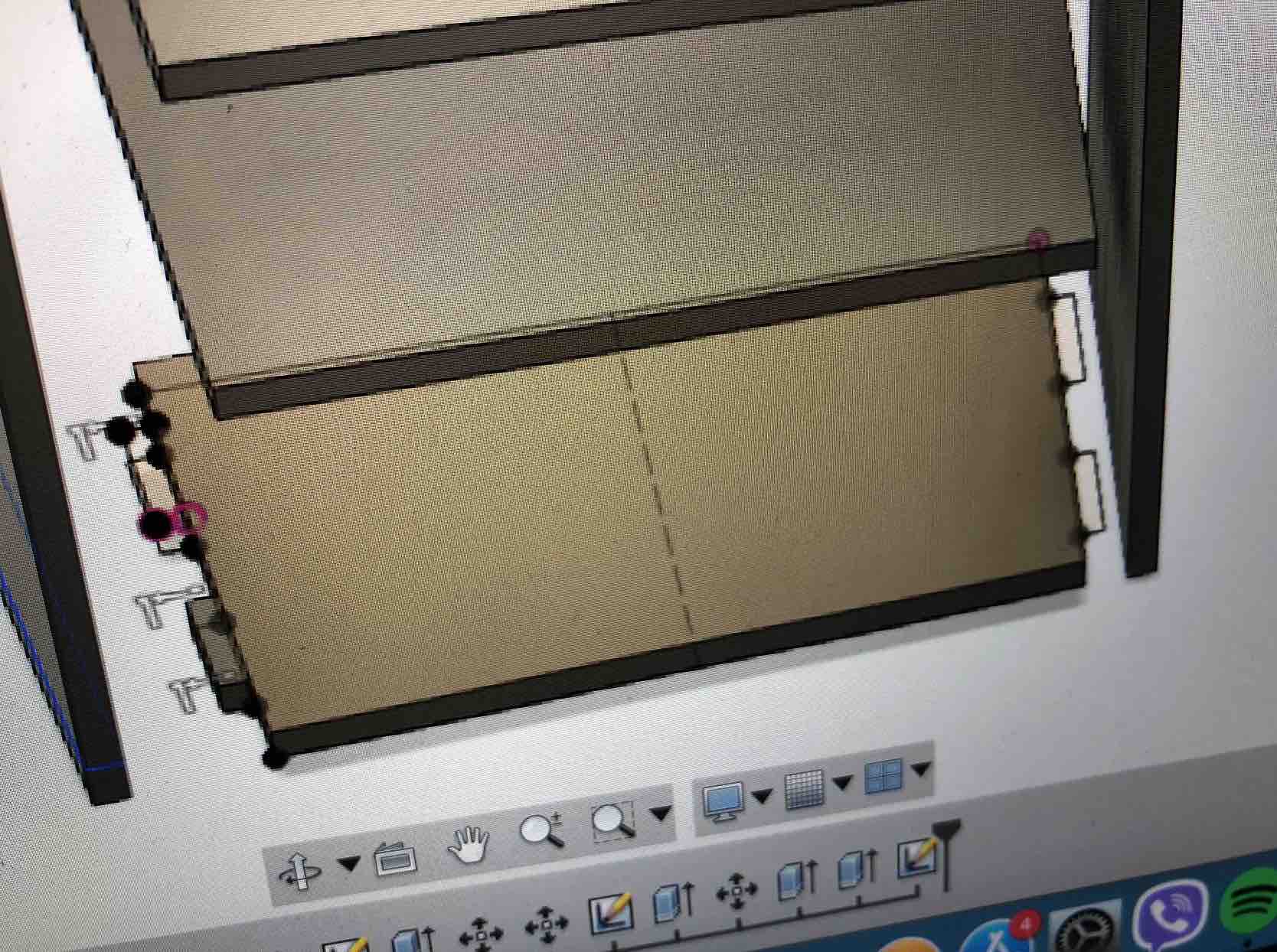
I had given up. Temporarily. It was then that I recalled some of the things Kyle taught me that I decided to try implement them. I rememberd the split body and split face tools. So I used them to rid the top parts of my side pillars, then extruded the middle up and downwards so that the pillar was back to its original height and had a flat surface at the top. I then used the mirror tool to mirror the construction of the pillars in the center and joined them both sides. Then just mirrored the pillar ontop the other side. It required some readjustments of the top to be a nice height and the bottom to not mean that there would be any or much strains on the bottom part of the shelf as initially there wasn't much space between the shelf itself and the ground.The below image is a screenshot of the new construction/now mirrored construction of the lower shelf.
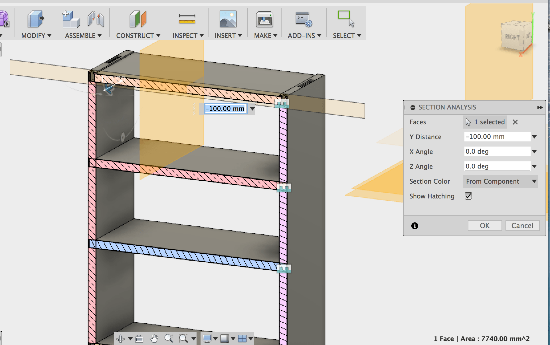
My next issue was that I couldn't figure out how to save the new shoe rack as a DXF file. And online I oculdn't find anything that I could understand or didn't require me to sit and wait for a download. Kyle explained to me that I could mirror my bodies onto a new sketch. For this I required to use the offset plane tool underconstruction. Luckily I was still able to print my shelf and even more luckier was that all the parts fit fine! This was a relief as my only way of knowing or hoping that they would is using by using the section analysis tool under the inspect window in Fusion.The below image
I did decide to change the construction slightly and use the tbone method. I did this because I thought since I was no longer using the japanese construction fully, I might as well try something new/use the other suggested method.
My shelves were tight enought that they requied force to put in with a hammer or lots of body weight, but loose enough that with some moderated and controlled force (as not to break it), you can pull it out, which is perfect as that's what I wanted it to be. This way I can take it apart if I need to move it or move places, and then put it back together easily.
Setting up the machine
Sidenote: if you want to stopthe warmup, press the RED button on the keyboard with the spinning disc on it.
sidenote: +- controlls the gantry's speed
sidenote: "F" + "13" takes gantry back to XY 0.
How do you ensure you've got the right tool? - Changing your tool
sidenote: a phone torch light from behind the tool cna be very useful here
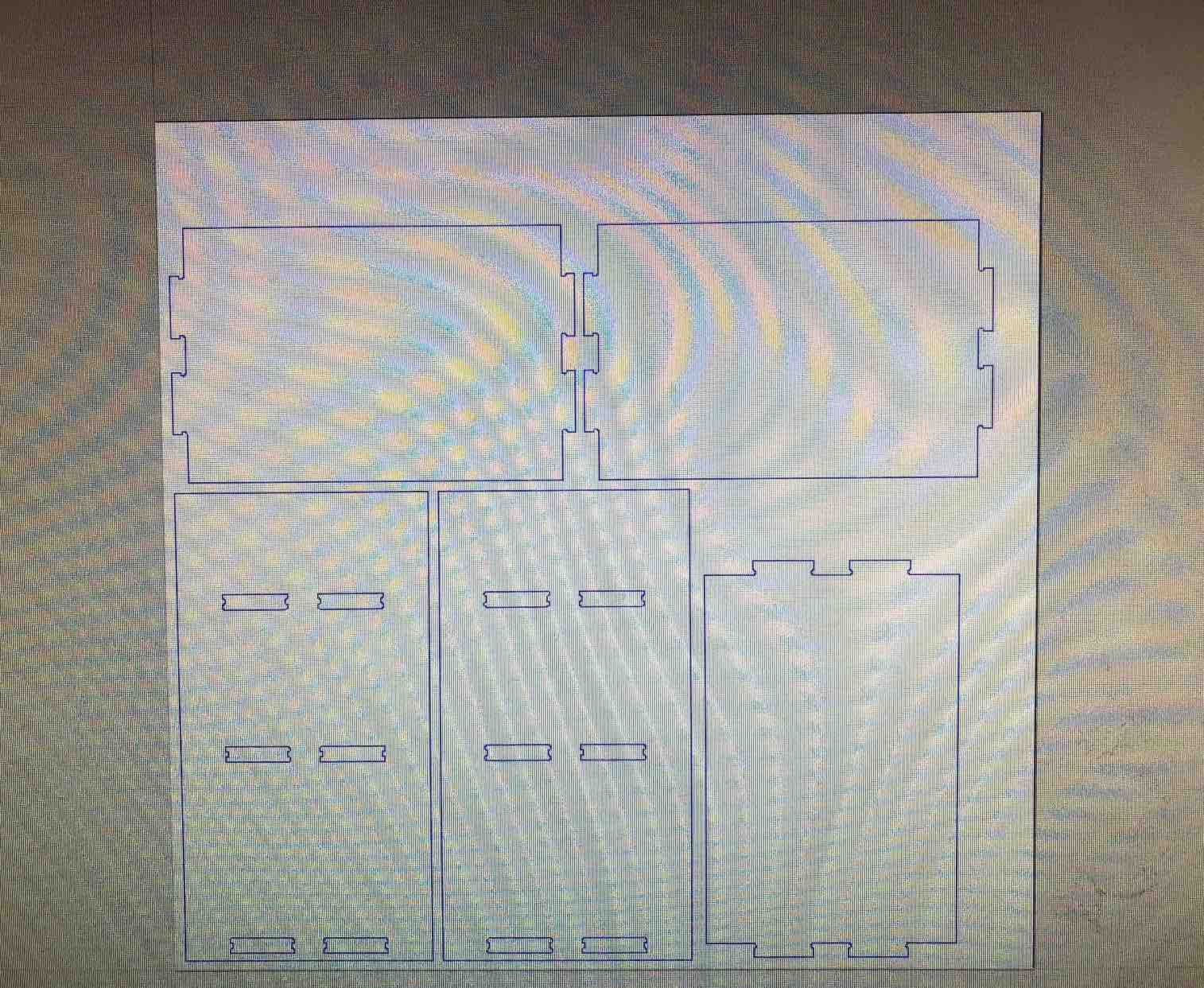
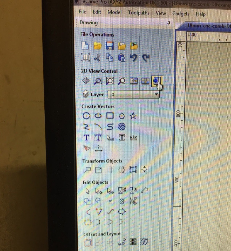
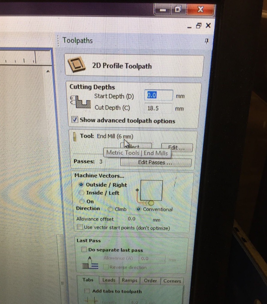
Using VCarve Pro Software to Generate Tool Path
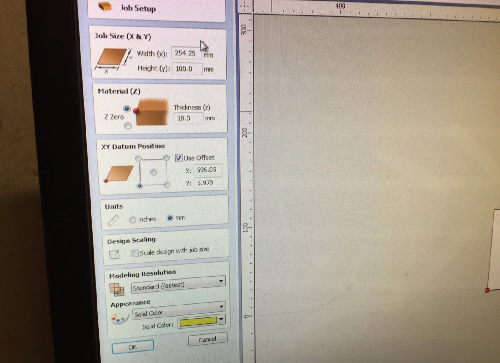
Please note: the measurements should be the size of your board or cutting area and NOT the full machine dimensions
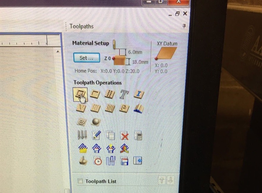
Make sure the default settings are kept, though you can opt to play withthe parameters cutting speeds and reducing the speeds
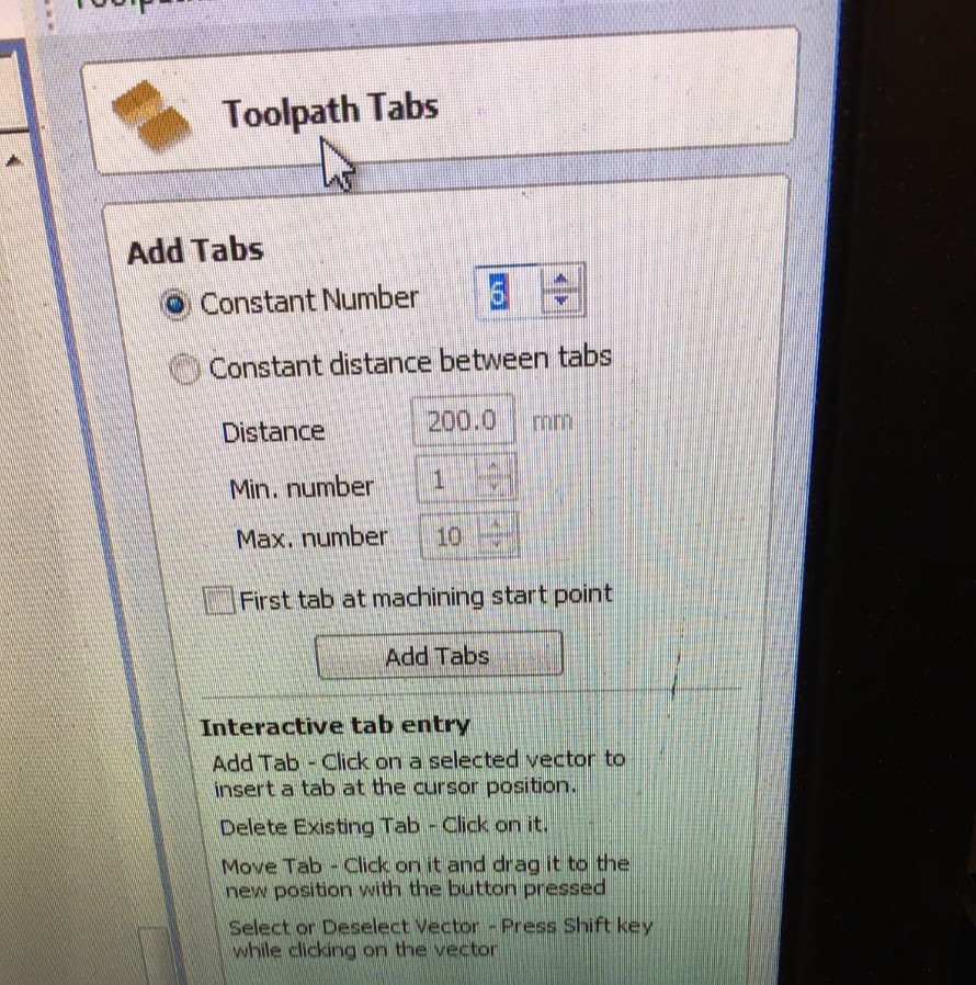
sidenote: you want to ensure you have plenty of tabs, as this makes the removal process much simpler and prevents the chances of having a hard to time to remove your piece and could cause breakage, but do not go too crazy and include a bunch of them!
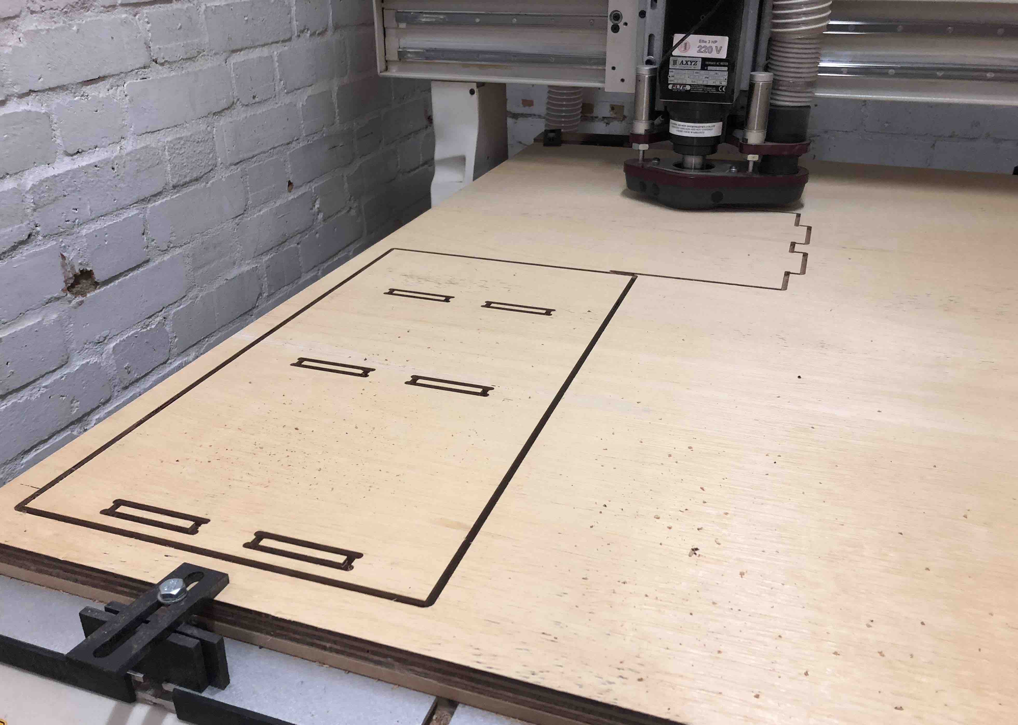
Cutting your something big
please note:
Removing your something big
In order to remove my shoe rack, I used a hammer and chiesel, and whacked away till i could pop off my masterpiece *insert cool face emoji*
How we tested our material
To test our material we went back to what we learnt at the start - combs. We cut out a comb as part of our group assingment, which we then used to test and see what size we should use when cutting so that we knew which size to use to keep our pieces fitted together tightly.
This weeks homework: